
TECHNICAL GUIDES / MANUFACTURER DIRECT
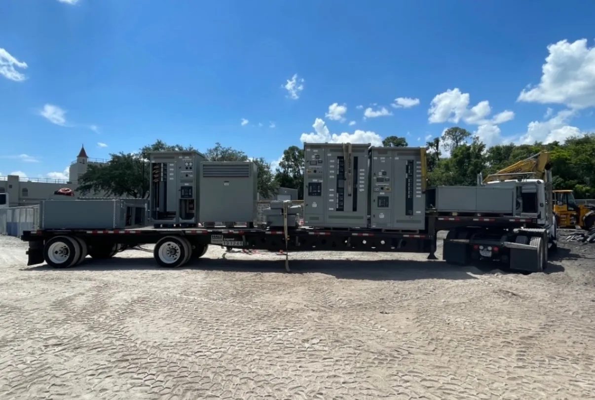
Switchgear engineering decisions connect the one-line diagram to the equipment, site interfaces, and operating plan. These guides explain how to frame questions about distribution equipment, protection, controls, documentation, testing, installation, and lifecycle choices before a project is finalized. Switchgear Builder Virginia manufactures new switchgear in the USA, using all-American components, with custom builds and nationwide shipping. Equipment configuration, ratings, schedules, and any applicable approvals must be confirmed for the specific project. Use these explainers to prepare for design discussions; qualified project professionals should establish and verify the final design.
Start with the System
Begin equipment selection with the system it must serve, not a catalog label. A one-line diagram, available utility information, load types, operating modes, and planned expansion help define what the switchgear must do. Record normal and alternate sources, tie arrangements, and which loads need to remain available during maintenance or an outage. These choices affect compartment layout, bus arrangement, control logic, and the information needed for a project quote. Do not assume two boards with similar ampere labels are interchangeable: voltage, fault duty, environmental conditions, and connection details can change the design. Bring unresolved assumptions to the engineer of record and equipment manufacturer early. Switchgear Builder Virginia can discuss custom new-equipment configurations; specific construction, ratings, and schedule remain subject to project review and quote. The approved drawings and specifications—not a general guide—must govern the finished selection.
Protection and Coordination
Protection choices should reflect the system study, the equipment being protected, and the consequences of an interruption. Ask the project engineer to document the applicable short-circuit information, protective-device settings, and coordination objectives, including any operating modes that change available fault current. A setting that supports selectivity in one configuration may behave differently after a source or tie changes. Confirm who supplies each protective device, who develops settings, and who verifies that the final arrangement matches the approved design. Do not infer interrupting capability or an assembly rating from a breaker frame size, a drawing symbol, or a guide example. Those details require project-specific documentation and verification. For a new switchgear quote, provide the latest study and device requirements where available, and identify open items clearly. Final protection decisions belong to qualified project professionals working from verified system data.
Controls and Interfaces
Control requirements are easiest to review when each signal has a defined purpose, source, destination, and expected response. Document local and remote commands, status points, alarms, interlocks, and any communications interface required by the project. Distinguish monitoring from control: a point that reports breaker position does not itself define who may operate the breaker or under what conditions. Coordinate control power, terminal locations, wiring responsibilities, and naming conventions with the switchgear drawings and the site control-system team. If automatic transfer or other sequences are specified, have qualified professionals verify the intended logic for normal, abnormal, and maintenance conditions before release. Features and interfaces vary by configuration and must be confirmed in the project documents and quote. A clear point list and approved elementary diagrams reduce ambiguity between equipment, field wiring, and controls integration without implying compatibility that has not been checked.
Drawings, Testing, and Installation
Submittal review should resolve the physical and electrical interfaces that can otherwise surface during installation. Check dimensions, access and working clearances, cable entry and termination space, conduit zones, lifting and handling assumptions, and the location of field connections against the project documents. Confirm which items are by the equipment manufacturer and which are by the installer or other project parties. Review the one-line, layout, schematics, and connection details together; a consistent label or device reference helps teams trace requirements across drawings. Ask the specification and quote to identify required inspections, tests, records, and approvals, and confirm who performs or witnesses each item. Do not assume a particular test, listing, or approval is included unless the project documents establish it. Applicable low-voltage switchboards may be specified as UL 891 assemblies; applicability and scope require verification. Installation and acceptance should follow approved documents and qualified direction.
Lifecycle and Procurement
Lifecycle planning starts with maintainability and future change, not just initial fit. Consider access to serviceable components, the documentation operators will need, spare-part identification, and whether planned load growth could affect space or ratings. For retrofit work, record the existing system conditions and interfaces, then have qualified professionals determine whether new equipment can meet the project requirements; do not assume existing dimensions or connections will transfer unchanged. For a new-equipment purchase, provide the manufacturer with a defined scope, required ratings, drawings, delivery location, and requested schedule so open assumptions can be identified before quote. Switchgear Builder Virginia offers direct USA manufacturing, custom builds, all-American components, short lead times, and nationwide shipping; actual configuration and schedule are subject to review and quote, not a delivery promise. Keep approved drawings, test records, and equipment identification together for future maintenance and engineering decisions.