
LOCATIONS / MANUFACTURER DIRECT
Switchgear Builder Virginia manufactures new switchgear in the USA using all-American components, with custom builds and nationwide shipping. For a hypothetical Winchester distribution facility, the equipment layout should account for warehouse feeder routes, changing loads and the relationship between switchgear and downstream distribution. Actual site conditions, equipment requirements, ratings and schedules need review before they are set in a quote. This guide outlines practical questions to resolve before specifying a system.
Map the feeder route
For a hypothetical distribution facility in Winchester, start the electrical layout by mapping the route from the service entrance to major load areas. Long interior runs can affect conductor sizing, voltage drop, installation labor and the space needed for supports or raceways. Do not choose equipment based only on a floor plan’s straight-line distance: verify the actual path around walls, doors, loading areas, structural members and other building systems. Identify where feeders branch, which areas may need future capacity, and whether equipment access can be maintained after operations begin. These details help the design team compare centralized switchgear with downstream distribution points. A manufacturer-direct quote can use the approved one-line diagram, load information and layout assumptions, but the design professional and project team must confirm the final routing, calculations and applicable requirements before equipment is specified.
Allow for changing loads
Warehouse demand can vary with the facility’s operating plan. A hypothetical distribution center might add conveyor sections, sorting equipment, charging areas or new process lines over time, but those possibilities are not a substitute for a documented load study. Ask the project team to distinguish connected load from expected demand, identify which equipment starts or operates together, and describe planned expansion in measurable terms. Then evaluate feeder and distribution arrangements against present needs and credible future scenarios. Extra capacity can provide flexibility, but oversized equipment may affect cost, footprint and coordination with the rest of the electrical system. Conversely, a tight initial layout can make later changes difficult. Confirm assumptions with the electrical engineer and equipment suppliers; have ratings, protective-device coordination, available fault current and other design requirements reviewed for the specific project rather than inferred from a general warehouse description.
Compare distribution options
Long warehouse runs may prompt a comparison between busway and cable-based feeder distribution. Busway can offer defined tap-off points and a compact route in suitable layouts, while cable systems may fit routes or installation conditions where busway is less practical. Neither option is automatically less expensive or better for every building. Compare the complete installed arrangement, including routing space, supports, access, branch locations, environmental conditions, future changes and coordination with switchgear. The [busway versus cable distribution comparison](/compare-busway-vs-cable-distribution) can help frame those questions, and [busway systems](/products-busway-systems) provides related product context. For a Winchester project, first verify actual run lengths, clearances, load locations and the design team’s preferred installation method. Busway system ratings and features are options to confirm against the application and quote, not assumptions established by the facility type.
Check layout and clearances
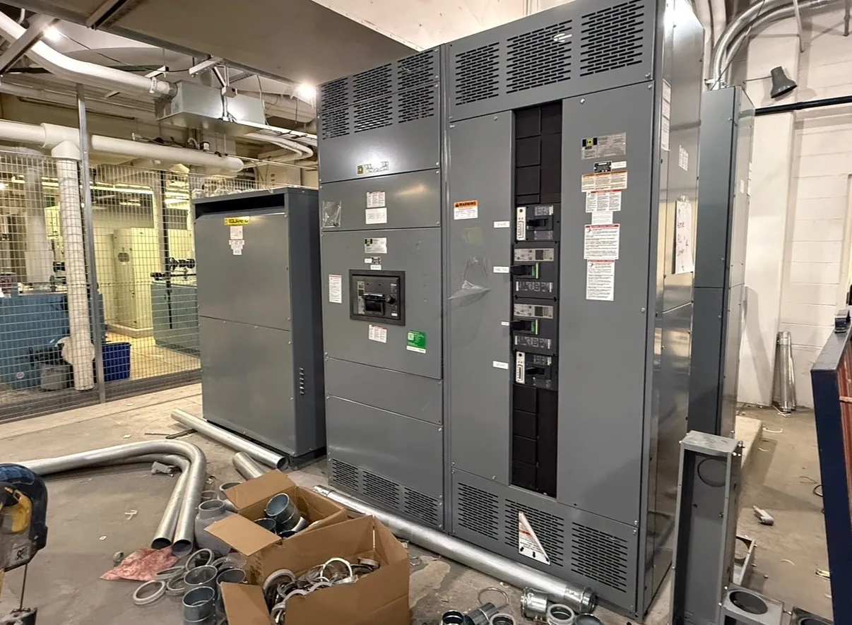
Before fixing a switchgear location, verify room dimensions, equipment access, working space, door swings, cable or busway entry points, ventilation needs and the route for moving equipment into place. The applicable electrical and building requirements depend on the project design and conditions, so the responsible design professionals should confirm required clearances and arrangements. In a hypothetical warehouse, an apparently convenient wall location could conflict with a loading route, future partition, sprinkler piping or another planned system. Coordinate the equipment outline and connection details with architectural, structural and electrical drawings rather than relying on a generic footprint. If the layout changes, revisit feeder routing and access before procurement documents are finalized. Switchgear Builder Virginia can consider a custom build using project-specific information; configuration, ratings, lead time and schedule remain subject to quote and verification, and no delivery date should be assumed until confirmed.
Prepare a quote package
A useful quote request includes the project location, desired equipment scope, one-line diagram, load and feeder schedules, available fault-current information, system voltage, incoming and outgoing requirements, site conditions and target procurement milestones. Include the approved room layout and any busway or cable-routing assumptions, while marking items that are still under design review. The [Winchester busway system planning page](/locations-winchester-busway-system-planning) covers the related local planning topic; local examples should be treated as hypothetical until site facts are verified. Use the [quote checklist](/request-quote) to organize project information and identify open questions. Switchgear Builder Virginia manufactures and supplies new equipment only, with USA manufacturing, all-American components, custom builds and nationwide shipping. UL 891 assemblies may be available where applicable to low-voltage switchboards; confirm the required construction and any ratings, approvals, testing, schedule and scope directly in the quote.