
APPLICATIONS / MANUFACTURER DIRECT
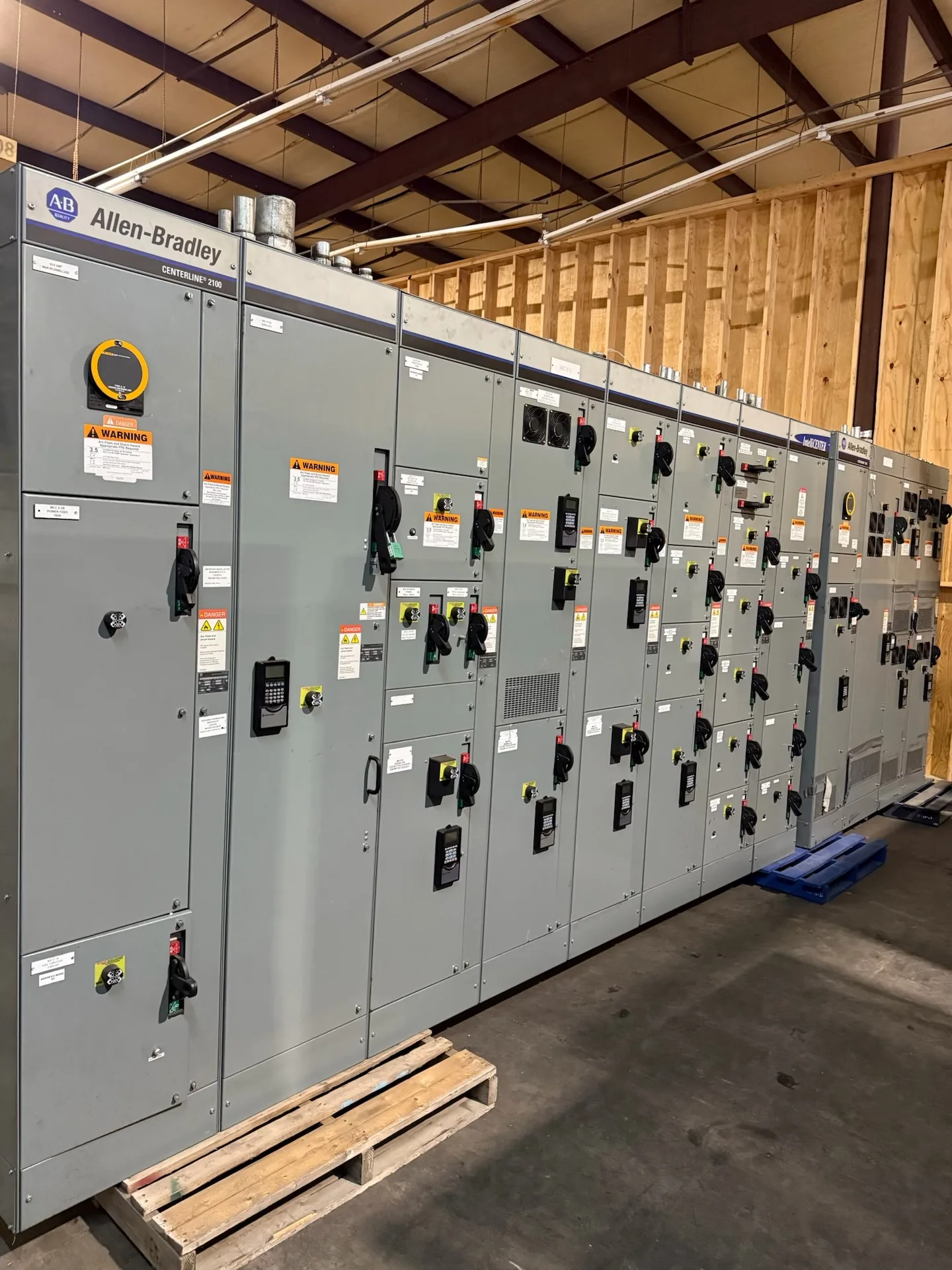
Battery storage interconnection switchgear connects a storage system’s power conversion equipment to an AC collection system, facility bus, or utility point of interconnection. The design must account for power moving in both directions: charging draws power, while discharge sends it outward. Switchgear Builder Virginia manufactures new, custom switchgear in the USA using all-American components, with nationwide shipping and short lead times subject to project scope and quote. Start by defining the electrical boundary, operating modes, and required protection. Then coordinate the one-line diagram, equipment ratings, controls, and project-specific requirements with the responsible engineer, utility, and other relevant parties.
Define the AC boundary
Battery interconnection switchgear handles AC-side functions; it is not the battery management system, inverter, or fire-protection system. First establish what equipment lies on each side of the switchgear: inverter or power conversion system, transformer if applicable, facility distribution, and the designated point of interconnection. That boundary determines which conductors enter the assembly, where isolation occurs, and which devices may need to coordinate. A project one-line diagram should identify normal and alternate sources, operating modes, grounding approach, and any ties to other buses. Do not assume every battery project uses the same arrangement: a behind-the-meter installation connected to a facility bus can differ substantially from a stand-alone plant. Switchgear Builder Virginia can build custom new equipment to a defined project scope; final configuration, ratings, and schedule require review and quote.
Plan for two-way power
Charging and discharging make power direction a design input, not a minor operating detail. Protection, metering, control logic, and device application must be reviewed against the intended import and export modes, including transitions between them. The engineer should identify expected current ranges, fault contribution, operating sequences, and how the installation behaves when a source or communications signal is unavailable. Do not infer a switch or breaker’s suitability from a nameplate voltage alone; interrupting duty, continuous current, short-time withstand, and system conditions need project-specific verification. The interconnection may also require operating limits or control functions defined by the utility or project documents. Those requirements are not established simply by specifying switchgear. Provide the manufacturer with approved one-line diagrams and equipment interfaces so the proposed assembly can be evaluated for the actual bidirectional application rather than an assumed one-way feeder.
Coordinate protection and isolation
Protection decisions depend on the complete system, not only the switchgear lineup. Identify the protective devices on the inverter, transformer, switchgear, and upstream system, then have the responsible engineer assess coordination, fault-clearing requirements, and settings against the project study and applicable interconnection requirements. Specify which device provides each required isolation point, how it is operated, and whether electrical or mechanical interlocking is required. A disconnect’s location and intended function should be clear on the drawings; similar-sounding devices may serve different boundaries or operating purposes. Also establish control power, trip signals, status indication, and any remote-operation requirements, if applicable. Do not treat a proposed feature as included until it appears in the reviewed scope. Switchgear Builder Virginia can evaluate custom configurations, while device selections, protective functions, approvals, and ratings remain subject to engineering review and quote.
Keep systems distinct
Battery management and fire-protection equipment perform functions separate from AC switchgear. Battery controls monitor cell or module conditions and may command the power conversion system; fire detection, suppression, ventilation, and emergency response arrangements are addressed through their own project design. The switchgear may receive defined status or trip interfaces where the approved design calls for them, but that does not make the assembly a battery safety system. Document the signals, responsible equipment, fail-safe behavior, and communications boundaries instead of relying on broad labels such as emergency shutdown. Confirm with the project team which party supplies wiring, interface relays, controls, and testing documentation. The physical arrangement also needs coordination with enclosure, cable-entry, access, and environmental requirements supplied for the site. These are project inputs to verify, not features to assume from a battery-storage application name.
Verify the submittal basis
Before release, align the one-line diagram, equipment schedule, control narrative, and interconnection documents. Confirm system voltage, continuous and fault-current requirements, bus arrangement, incoming and outgoing connections, enclosure conditions, metering provisions, and any specified communications or interlocks. Where the project calls for low-voltage switchboard construction, UL 891 applicability and the required assembly details should be confirmed for that scope; it does not describe medium- or high-voltage switchgear. Any inspection, testing, listing, or approval requirement should be stated and verified for the exact equipment and project, rather than presumed. Switchgear Builder Virginia manufactures new assemblies in the USA and ships nationwide. Lead time depends on the defined scope and schedule review, so request a project-specific quote after drawings and requirements are sufficiently established. This gives buyers a clearer basis for comparing configuration, interfaces, and responsibilities.