
APPLICATIONS / MANUFACTURER DIRECT
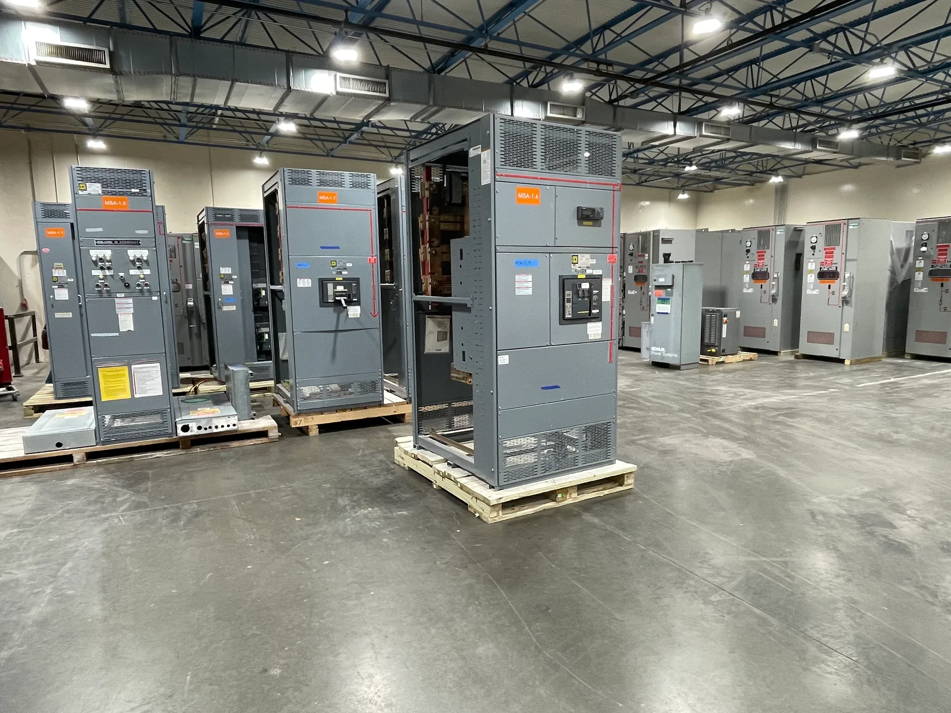
Facility expansion can turn a workable electrical service into a constraint—or reveal that the real limit is space, feeder arrangement, or coordination with existing equipment. Switchgear Builder Virginia helps buyers define the distribution scope for new loads by reviewing available project information and developing a custom build around verified requirements. Start with existing drawings, equipment nameplates, and the expansion’s load details. These records help frame questions for the engineer, utility, and equipment supplier; they do not, by themselves, establish spare capacity or an approved design. Final equipment configuration, ratings, schedule, and applicable approvals must be confirmed for the specific project before release.
Find the constraint
Begin with the service and distribution path that would supply the expansion, not just the proposed new equipment. Existing one-line diagrams, service and switchboard nameplates, available load records, and feeder schedules can help the design team compare present demand with the planned loads. A nameplate rating is not proof that spare capacity is available: bus limits, protective-device settings, conductor sizes, fault-current conditions, operating patterns, and applicable design requirements also matter. Have the responsible electrical engineer determine what capacity can be used and whether the utility or authority having jurisdiction must review changes. If records are incomplete, identify what needs field verification by qualified personnel before selecting equipment. A clear constraint assessment can distinguish a new feeder or section from a larger service change, avoiding a premature assumption that the existing board can simply accept another load.
Define new feeders
List each planned load, its expected operating profile, connection point, and required voltage and phase, as applicable. Identify whether loads are continuous, motor-driven, cyclical, or likely to start together; these characteristics can affect feeder sizing and protective-device coordination. The project engineer should establish conductor, breaker, and bus requirements from verified load calculations and site conditions, rather than treating a preliminary equipment schedule as final. Also clarify which loads need dedicated feeders, spare provisions, metering, or selective coordination, and whether the expansion requires maintainability or separation between functions. These choices influence section layout, space, cost, and future flexibility. Leave ratings and device selections open until the responsible design parties confirm them. When requesting a custom switchboard, provide the approved one-line diagram and feeder schedule when available, and flag unresolved loads so the quote can state assumptions instead of implying that every requirement is settled.
Check space and access
A distribution lineup must fit the intended electrical room and remain accessible for installation, operation, and maintenance under the project’s verified requirements. Share room dimensions, door and corridor clearances, ceiling height, existing equipment locations, cable entry direction, and likely routing paths. Confirm whether the available footprint includes working space and access requirements established by the project’s engineer and applicable authorities; do not assume that an open wall means a lineup will fit. Consider shipping and handling routes, floor conditions, anchorage, and room changes that may be part of the expansion. If existing drawings are outdated, have qualified personnel verify dimensions and interfaces before releasing fabrication information. A custom build can address project-specific arrangement needs, but customization cannot resolve a site conflict that has not been identified. Early space checks help buyers compare a compact lineup with a more expandable arrangement and understand the practical tradeoffs.
Plan the interface
Expansion work has to connect new distribution with existing service equipment and the broader project design. Provide available one-line drawings, equipment schedules, interface details, and any documented utility or engineer requirements. The design team should verify system voltage, phase, frequency, available fault current, grounding approach, protective-device coordination, and connection method before equipment ratings are selected. Existing bus dimensions or an older drawing should not be treated as confirmation that a new section can connect directly. Where a tie-in or shutdown is contemplated, the responsible project team must plan it around site procedures and qualified personnel; this page is not a live-work procedure. Clarify who supplies conductors, transitions, controls, metering, and field connections, since unclear boundaries can create scope gaps. For applicable low-voltage switchboard assemblies, UL 891 requirements may be relevant; applicability and any required listing or approval must be confirmed for the actual project.
Prepare the quote
A useful quote request brings the project’s known facts together while separating them from open design decisions. Send existing drawings and nameplate information, the proposed load list, required feeder count, room and access details, connection preferences, and the desired expansion sequence. Note which information is preliminary and identify the engineer or other party responsible for final ratings and approvals. Ask the supplier to identify assumptions, exclusions, interface responsibilities, and information needed before production; compare those items alongside the proposed configuration. Switchgear Builder Virginia manufactures new custom equipment with all-American components, direct USA manufacturing, and nationwide shipping. Lead time and schedule depend on the confirmed scope and must be reviewed for the quote; no delivery date should be inferred from a preliminary discussion. Ratings, assembly details, applicable UL 891 requirements, and other project-specific conditions remain subject to verification before order and release.