
APPLICATIONS / MANUFACTURER DIRECT
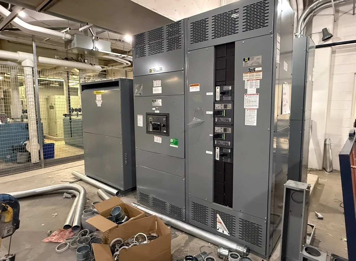
A legacy equipment interface starts with evidence from the installed system, not assumptions based on a cabinet’s appearance. Nameplates, dimensions, drawings and bus details help define what a new assembly must connect to and what needs further investigation. Switchgear Builder Virginia manufactures new, custom switchgear in the USA using all-American components, with nationwide shipping. Before selecting an interface, the project team should reconcile field measurements with available documents, then verify electrical ratings, mechanical clearances and connection requirements against the actual installation.
Start With Identification
Record each available nameplate clearly, including manufacturer, model, serial information, voltage, current, frequency and interrupting or withstand ratings where shown. Photograph the full label and its mounting location; a partial image may omit a suffix or rating that distinguishes one assembly from another. Note which section, compartment or device the label identifies, because a lineup can contain components with different functions and ratings. If a label is damaged, missing or inconsistent with drawings, mark that fact rather than filling in a likely value. Treat remembered specifications and old schedules as leads to verify, not as confirmed data. This inventory gives the designer a starting point for determining what the new equipment must serve, what characteristics remain unknown and which questions need resolution before a proposed interface can be evaluated.
Measure the Installation
Capture enclosure width, height and depth, section boundaries, access clearances, door swing and the locations of cable entry and existing connections. Measure from consistent reference points and note whether dimensions include trim, plinths, barriers or projecting hardware. Record the available route for moving new equipment into the electrical room, since a cabinet that fits its final footprint may still be difficult to bring through a doorway or around an obstruction. Note nearby walls, overhead services and working space for review by the project’s qualified design team; do not infer code compliance from a tape measure alone. Provide photographs with a scale or marked dimensions where practical. These observations help distinguish a dimensional interface problem from an electrical one, while leaving final fit, clearances and installation requirements subject to drawing review and site verification.
Document the Connections
Gather current and legacy one-line diagrams, control schematics, wiring diagrams, equipment schedules and revision notes, if available. For bus connections, document orientation, phase arrangement, elevation, width, thickness, hole pattern and access, but have a qualified person verify measurements and material details before they become design inputs. Identify cable sizes and termination locations from reliable records or an approved field survey; do not assume that visible conductors reveal the complete circuit arrangement. Track grounding and neutral connections, control power, metering, interlocks and auxiliary contacts as separate interface questions. Mark drawings with known discrepancies instead of silently combining information from different revisions. A coordinated set of records helps the manufacturer evaluate a proposed transition, identify missing data and clarify whether a custom assembly or a different connection approach should be considered.
Verify Ratings and Fit
Mechanical alignment alone does not establish that two assemblies are electrically compatible. Compare the documented system voltage, continuous current, available fault current, protective-device characteristics and bus requirements with the proposed equipment design, using project-specific engineering review. Confirm the intended grounding arrangement and the function of each feeder, main and tie; labels such as “main” or “spare” do not establish how a circuit is protected. Ratings and construction details for the new assembly must be specified and verified for the application before release. If records conflict, a rating is unreadable or the existing equipment has been modified, pause that assumption and resolve it with the responsible engineer. Applicable low-voltage switchboard requirements, including UL 891 where relevant, should be confirmed for the specific assembly; that standard does not apply to medium- or high-voltage equipment.
Define the Interface Scope
A useful project package separates confirmed facts, field observations and open questions. Include the equipment inventory, dimensioned photographs, available drawings, bus and cable details, operating sequence, required circuits and any known access constraints. State what the new assembly is expected to connect to, what existing components remain and who will verify site conditions. Ask the design team to identify the transition boundary, required terminations, protection coordination inputs and any control changes before equipment is specified. Switchgear Builder Virginia can use project information to discuss a custom new-equipment scope; configuration, ratings, schedule and suitability remain subject to quote, engineering review and verification. The company manufactures in the USA, uses all-American components and ships nationwide. Clear scope definition reduces avoidable assumptions, but does not replace approved drawings, qualified installation planning or confirmation that the completed interface matches the project requirements.