
APPLICATIONS / MANUFACTURER DIRECT
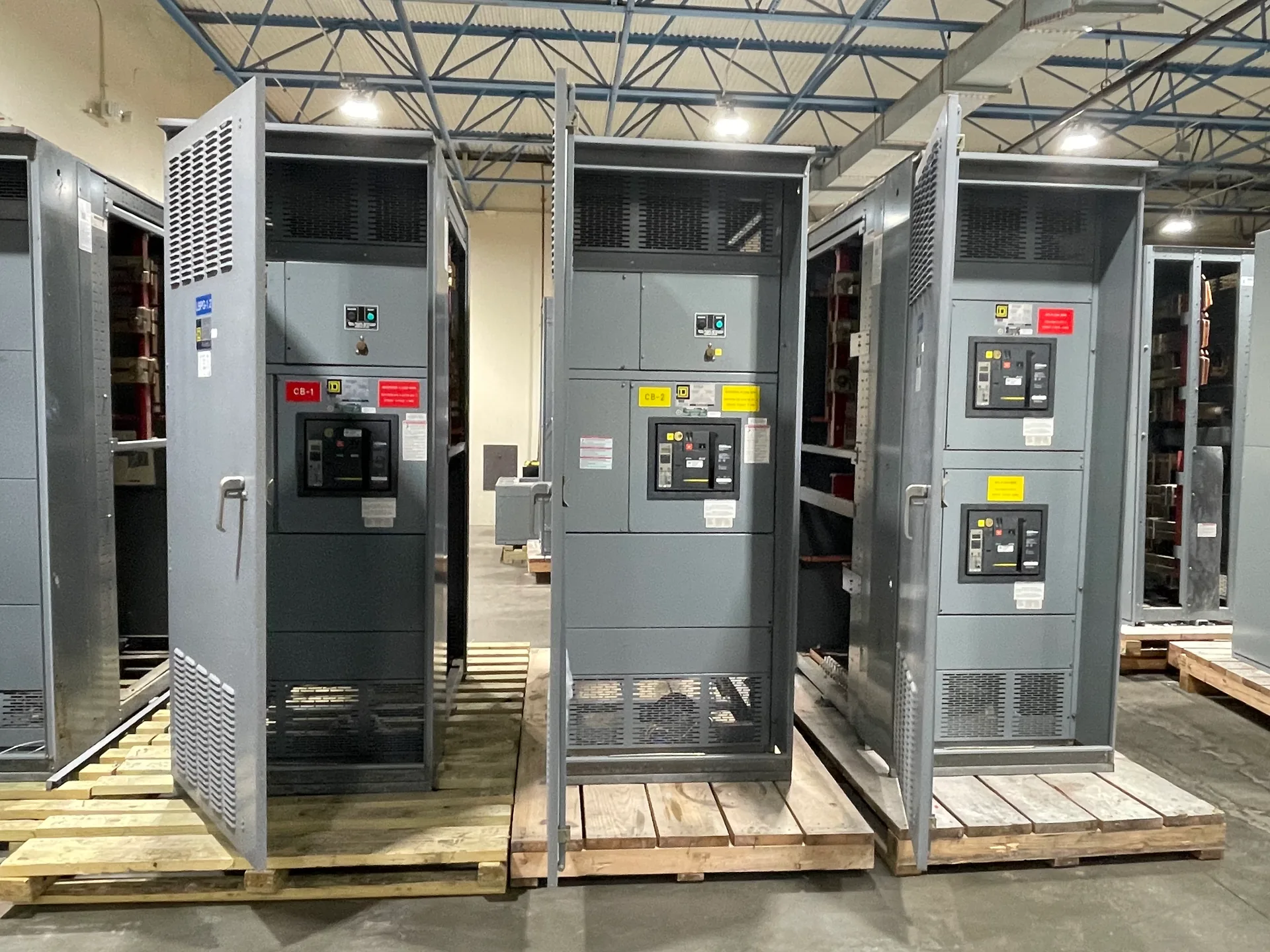
Permanent generator integration is a coordination problem as much as an equipment selection. The generator breaker, transfer or paralleling arrangement, switchgear bus, controls, and protective settings must work together within the facility’s operating plan. Switchgear Builder Virginia manufactures custom new switchgear in the USA using all-American components, with nationwide shipping and short lead times subject to project scope and quote. Use the requirements below to define interfaces early; final equipment, ratings, schedules, and responsibilities must be confirmed for the specific project.
Choose the Operating Arrangement
Start by defining what the generator must do: serve selected loads after utility loss, operate alongside the utility where permitted, or support multiple generators through a paralleling arrangement. Those goals lead to different one-line diagrams, switching sequences, and equipment interfaces. An automatic transfer switch (ATS) typically transfers a load between sources; paralleling equipment coordinates sources that may operate together. They are not interchangeable solutions. The engineer and project team should identify the normal source, alternate source, intended load groups, transition behavior, and whether any closed-transition or utility-parallel operation is required. These choices affect the generator breaker location, bus configuration, control logic, and protection coordination. Provide the design intent and current one-line diagram before requesting a switchgear quote, so the proposed lineup can be evaluated against the actual operating sequence rather than an assumed application.
Set Equipment Boundaries
A clear responsibility matrix prevents gaps between the switchgear manufacturer, generator supplier, ATS or paralleling-equipment supplier, controls integrator, electrical contractor, and commissioning provider. Identify who supplies each breaker, controller, relay, instrument transformer, communications interface, and interconnection cable. Then document who provides wiring diagrams, control descriptions, terminal schedules, settings, and approved submittals. Confirm whether equipment arrives as a coordinated assembly or as separate packages requiring field interconnection. The quote should distinguish included equipment from items furnished by others; the project team should also clarify who reviews interfaces and resolves discrepancies. Switchgear Builder Virginia can develop custom new switchgear to defined project requirements, but generator equipment, transfer controls, programming, field wiring, and commissioning should not be assumed included unless the written scope says so. Agreeing on these boundaries early helps buyers compare proposals on equivalent scope and identify missing work before installation planning.
Coordinate Protection and Ratings
Protection settings depend on the generator, connected loads, utility source, grounding method, available fault current, and the selected operating modes. The design team should coordinate generator and feeder protection with switchgear breaker functions and any transfer or paralleling controls. Confirm required voltage, frequency, continuous current, interrupting capacity, withstand capability, and system configuration against project documents and manufacturer data; do not infer a rating from a generator size alone. Review whether motor starting, transformer inrush, or load shedding affects the intended sequence. Identify who calculates, supplies, reviews, and enters settings, and what documentation is required for approval. Settings and ratings remain subject to engineering review and quote verification. For applicable low-voltage switchboard assemblies, UL 891 may be relevant; it does not establish generator suitability or replace project-specific evaluation of the complete system and its interfaces.
Define Controls and Signals
Translate the operating sequence into specific control actions and signals. The sequence may address utility failure detection, generator start request, acceptable source conditions, transfer permissives, breaker close and trip commands, retransfer, cooldown, and alarm reporting. The exact steps depend on the selected equipment and project design; avoid relying on a generic sequence when the facility has critical loads or multiple operating modes. List each hardwired point and communications requirement, identify signal ownership, and confirm voltage levels, contact types, protocol, and fail-safe behavior with the relevant suppliers. Determine what happens if a controller, communication link, or source fails, and document the expected response for review. Clear control narratives and point lists give the switchgear, generator, and ATS or paralleling suppliers a common basis for submittals, wiring, and acceptance planning without assuming that one supplier provides every control function.
Plan Reviews and Handoffs
Before release, align the one-line diagram, equipment schedules, control narrative, protection study, and supplier drawings. Resolve differences in breaker designations, terminal references, sensing points, and operating modes before fabrication or field wiring. Establish who reviews submittals, who authorizes setting changes, and who witnesses each planned inspection or test; required procedures and approvals depend on the project, equipment, and authority having jurisdiction. Commissioning scope should name the party responsible for generator startup, transfer or paralleling checks, protective-device verification, sequence testing, and final records. Switchgear Builder Virginia can quote custom new assemblies against documented requirements, with schedule and ratings verified for the order. Nationwide shipping is available, but site coordination, field installation, programming, testing, and commissioning are separate responsibilities unless explicitly included in the agreed scope.