
FAQ / MANUFACTURER DIRECT
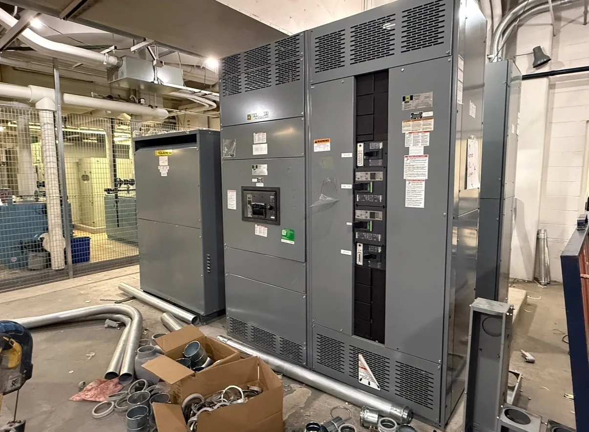
A switchboard can be designed to accommodate utility metering, but the answer depends on the serving utility’s rules and the project’s electrical arrangement. Metering may affect current transformers (CTs), compartment space, wiring, access and the boundary between utility-controlled and customer equipment. Switchgear Builder Virginia builds custom new switchboards in the USA with all-American components; the proposed configuration, ratings, schedule and utility acceptance must be confirmed for each project. Start by checking the utility’s current metering requirements, then coordinate those details with the switchboard design before the assembly is quoted.
It Depends on the Utility
Utility metering is not a single standard arrangement that fits every switchboard. The serving utility may specify where its meter is mounted, which conductors are metered, how the service is arranged, and what access or separation it requires. Some projects may use utility-supplied metering equipment or a defined meter socket arrangement; others may call for instrument transformers and an approved metering compartment. These choices can affect the switchboard layout, cable routing, compartment dimensions and service entrance configuration. The utility’s rules, not a generic product description, determine whether a proposed interface is acceptable. Before design, identify the actual serving utility and obtain its current requirements for the project voltage, service type and anticipated current. Switchgear Builder Virginia can review those project inputs when developing a new custom switchboard, but utility eligibility and acceptance must be confirmed with the utility and documented for the specific assembly.
CTs and Metering Circuits
Current transformers, or CTs, scale line current so compatible metering equipment can measure it. Their selection and arrangement depend on system voltage, expected current, conductor configuration, metering purpose and the utility’s specified equipment. The design may need space for CTs around bus or conductors, appropriate support and clearances, secondary wiring routes, and an accessible location for the meter interface. CT ratio, accuracy class, burden, polarity and terminal details should not be guessed from a general load estimate; confirm them against the utility’s requirements and the project documents. The utility may furnish or approve particular components, and may control how CT secondaries are connected or accessed. Those details can change the compartment plan and wiring scope, so resolve them before layout approval. Any proposed CT arrangement, component ratings and metering provisions remain subject to review against the final one-line diagram, utility criteria and quoted assembly configuration.
Space, Access and Boundaries
A metering section needs more than a place to mount a meter. Designers may need to allow for utility access, doors or covers, instrument-transformer clearances, wiring separation, conductor bending space and a practical route for service conductors. The utility may also require a specific compartment boundary between equipment it owns or controls and customer-owned switchboard sections. That boundary can influence lineup length, section placement, barriers, termination points and the locations of other devices. Requirements vary, so do not assume that a familiar arrangement from another site will be accepted at this one. Provide the switchboard manufacturer with the utility’s metering drawing or written criteria, available room dimensions, service entrance details and project one-line. If space is constrained, discuss the tradeoffs early: moving metering can affect cable paths, access and adjacent equipment. The final design should reflect verified project conditions and utility requirements, not a presumed standard layout.
Utility Review and Assembly Scope
Utility review is separate from deciding whether a switchboard can physically house metering components. The utility may require submittals, drawings, component details, inspection steps or written acceptance before service connection; the exact process and authority depend on the project. Confirm who supplies the meter, CTs, meter socket, test switches and related wiring, and who installs or terminates each item. Clarify responsibilities among the utility, electrical contractor, engineer and equipment manufacturer so that no required interface is omitted or assigned twice. For applicable low-voltage switchboards, UL 891 assembly requirements may also be relevant, but that does not establish utility acceptance or approval of a particular metering arrangement. Switchgear Builder Virginia can consider the requested metering provisions in a custom new assembly, subject to review and quote. Any inspections, tests, approvals, listings or utility acceptance should be treated as requirements to verify for the specific configuration, not assumed from the general product type.
What to Confirm Before Quoting
To evaluate a metering-ready switchboard, gather the serving utility’s current metering standard, the project one-line diagram, nominal voltage, service type, estimated load or specified current, available fault information and site constraints. Include any utility notes about CTs, meter location, compartment access, ownership boundaries, supplied components and required submittals. Ask the electrical engineer or utility contact to resolve open questions before the equipment layout is finalized. These inputs help determine whether the requested interface can fit the lineup and what details must be included in the quote; they do not by themselves confirm eligibility or acceptance. Switchgear Builder Virginia manufactures new custom switchgear in the USA, uses all-American components, and ships nationwide. Lead times and ratings are subject to quote and verification. The practical next step is to compare the utility’s documented requirements with the proposed assembly and confirm unresolved details before releasing the design for production.