
GLOSSARY / MANUFACTURER DIRECT
A main disconnect is the device intended to interrupt the supply feeding equipment or an assembly. Its location and arrangement affect how a system can be isolated for operation, maintenance, or an emergency, but the term does not identify one universal device or layout. The right configuration depends on what the equipment serves, how the supply is arranged, the project specifications, and applicable rules. Switchgear Builder Virginia manufactures new, custom-built switchgear in the USA using all-American components, with nationwide shipping and short lead times subject to quote and verification. This guide explains the term and the project questions buyers should resolve before specifying an assembly.
What the term means
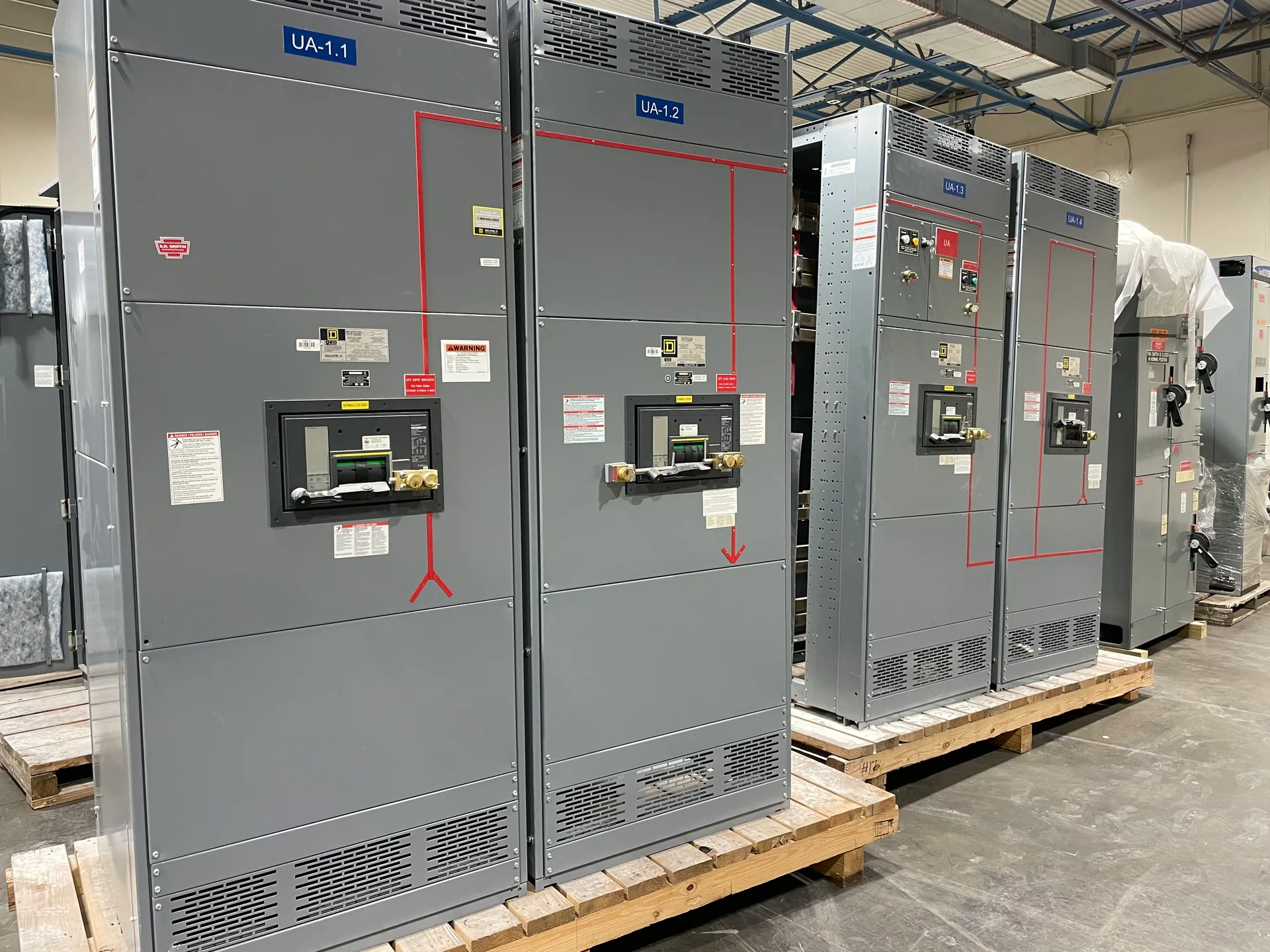
A main disconnect is the device designated to disconnect the supply to a piece of equipment or an assembly. Depending on the application, it may be a circuit breaker, a switch, or another permitted device selected for the system. “Main” describes its role in the arrangement; it does not, by itself, establish the device’s rating, construction, location, or suitability for a particular installation. The disconnect may be part of a switchboard or other assembly, or it may be arranged separately, as allowed by the project design and governing requirements. Buyers should identify exactly which equipment the device is intended to isolate and which source or sources feed that equipment. That shared definition helps the owner, engineer, contractor, and manufacturer discuss the same boundary instead of relying on an ambiguous label on a drawing or equipment schedule.
Why it matters
The main disconnect defines an important boundary in the electrical system. When its role and position are clear, project teams can coordinate the equipment layout, incoming supply, downstream distribution, operating procedures, and space needed for the assembly. If the disconnect is omitted from early planning or shown with unclear scope, drawings and equipment schedules may disagree about what is included, where supply conductors terminate, or which loads are served. Those questions can affect enclosure arrangement and connections, so they are best resolved before a custom assembly is released for manufacture. A main disconnect is not a substitute for a complete safety program, nor does its presence alone establish that every conductor or energy source is isolated. Project documents should describe the intended function and interfaces, with qualified professionals determining how the installation is designed and operated under applicable requirements.
Configurations depend on the job
There is no single main-disconnect configuration that fits every project. The required arrangement can depend on the equipment’s function, supply characteristics, connected loads, system architecture, available space, and governing rules. Some designs may place a main device within a low-voltage switchboard; others may use a different permitted arrangement. The number and placement of devices, how incoming and outgoing circuits are organized, and whether additional sources or transfer equipment are involved all need project-specific review. A specification should avoid treating a familiar one-line diagram or a previous installation as automatically suitable for a new job. Instead, identify the intended supply boundary, operating needs, and interfaces, then have the responsible design team confirm the configuration. Where a low-voltage switchboard is specified, UL 891 may apply to the assembly; applicability and any required listing or verification must be confirmed for the actual product and project.
What buyers should specify
For a useful quote, provide the latest available one-line diagram, equipment schedule, project specifications, and known supply and load information. Clearly state what the main disconnect is expected to serve, where the equipment will connect, and whether the project requires a particular device type, arrangement, enclosure, or accessory. Identify constraints such as available installation space and planned connections, while marking details that remain subject to engineering review. Ask the project engineer or authority having jurisdiction to resolve governing requirements rather than assuming a label or standard configuration settles them. These inputs help the manufacturer distinguish firm requirements from open decisions and identify questions before drawings are finalized. Switchgear Builder Virginia can discuss custom new equipment and provide schedule and rating details by quote and verification; no rating, approval, or delivery date should be inferred from the term “main disconnect” alone.
Coordinate isolation and scope
A disconnect’s intended isolation function should be coordinated with the complete installation, not evaluated as a standalone label. Teams should account for all relevant supply sources and connected equipment in the design documents, and establish clear identification and operating procedures through the responsible professionals. If existing gear is being replaced or a system is being modified, document the current arrangement and interfaces so the new equipment can be evaluated against actual project conditions; do not assume an old drawing accurately represents the installation. Any inspection, testing, approval, or listing needs should be stated and confirmed for the specific scope rather than presumed. Switchgear Builder Virginia manufactures and supplies new switchgear, with direct USA manufacturing, all-American components, custom builds, and nationwide shipping. For applicable low-voltage switchboard projects, UL 891 requirements can be addressed when relevant and verified. Final device selection, ratings, configuration, and schedule remain subject to project review and quote.