
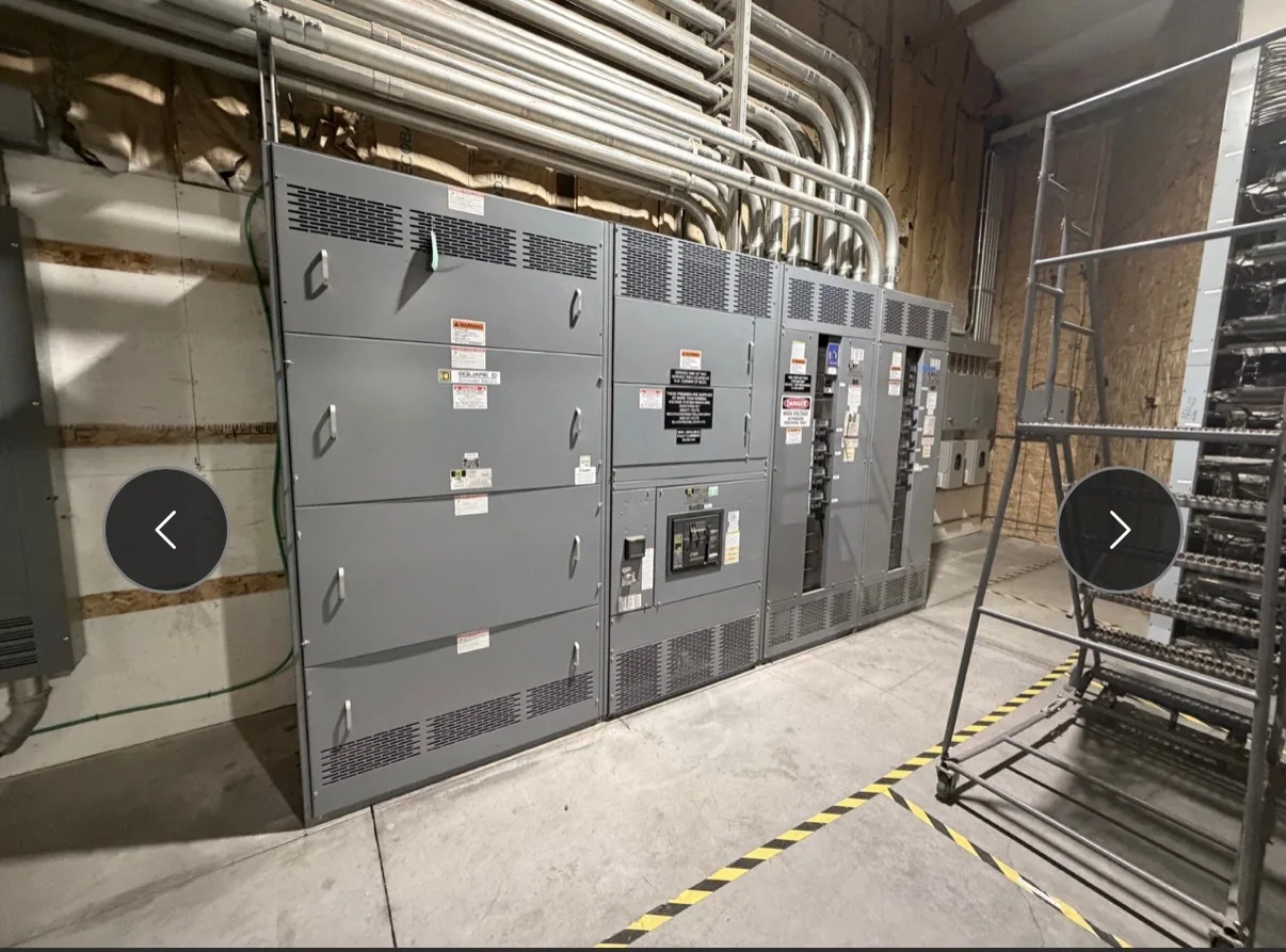
APPLICATIONS / MANUFACTURER DIRECT
Critical load distribution starts with a clear account of what must remain available, what may pause, and how each load is supplied. Switchgear Builder Virginia can develop custom new equipment around documented project requirements, with direct USA manufacturing, all-American components, and nationwide shipping. The design discussion should include normal and alternate sources, maintenance conditions, and the consequences of losing individual sections. Those decisions shape the lineup, protective-device coordination, metering, and provisions for future changes. Ratings, schedules, and any required approvals must be established and verified for the specific project before they are treated as design inputs.
Rank Essential Loads
Begin with a load list that identifies what each circuit serves, how much interruption it can tolerate, and who owns the operating decision. A data room, process pump, life-safety panel, and general receptacle circuit may all matter, but they do not necessarily belong on the same priority tier. Record normal demand, starting behavior, expected growth, and whether loads can be shed or restarted in sequence. Ask the owner to define what “available” means in practical terms: no interruption, a brief transfer, or restoration after a planned response. These distinctions affect distribution boundaries and operating procedures, not just breaker selection. The list should also identify loads that share a common upstream dependency, so apparent redundancy does not hide a single point of failure. Confirm assumptions with the electrical engineer and facilities team before translating priorities into equipment requirements.
Map Source Paths
Trace every critical circuit from its source through the proposed distribution equipment to the served load. Show normal and alternate sources only where the project actually provides them, and identify transfer equipment, ties, transformers, and downstream panels as applicable. A second source does not by itself establish an independent path: both routes may depend on a shared bus, room, control supply, or upstream device. Document which components are common, which can be isolated, and what the operating sequence requires. The one-line diagram should make source selection and tie positions understandable to operators, while the equipment arrangement should allow the intended switching sequence without implying capabilities that have not been specified. Confirm source voltage, available fault current, grounding method, and system configuration with project stakeholders and design records. Final ratings and protection settings require project-specific engineering verification.
Plan Maintenance Conditions
Reliability objectives should include maintenance, not only normal operation and emergency response. Ask which sections or devices must be inspected, isolated, or replaced while other critical loads remain supplied. The answer may influence bus segmentation, compartment arrangement, access clearances, spare provisions, and the location of isolation points. Each added boundary or alternate path can support a maintenance strategy, but it can also add cost, operating complexity, and opportunities for incorrect switching. Define who is authorized to operate the equipment and what status information they need to confirm before changing source or tie positions. The project team should evaluate maintenance procedures and electrical safety requirements using qualified personnel and applicable documentation; equipment design does not replace those procedures. Where continuity during maintenance is a stated objective, specify the required scenario and have the engineer confirm that the complete system—not just one lineup—supports it.
Document Failure Scenarios
Turn broad reliability goals into specific failure scenarios that can be reviewed. Consider loss of a source, a feeder fault, a bus-section outage, failed control power, a transfer device unavailable for service, or a planned shutdown. For each case, record which loads are lost, what can be transferred or shed, who responds, and what conditions permit restoration. Include the owner’s acceptable interruption and recovery expectations rather than assuming every critical load has identical needs. This review can reveal that two supposedly separate paths share a vulnerable component, or that a proposed tie cannot carry the intended load. It can also identify where alarms, metering, communications, or clear operating labels would help diagnose a condition. Treat these as project requirements to evaluate, not as standard features or verified performance claims. The design team should confirm each scenario against the complete electrical system.
Translate Goals Into a Lineup
Once priorities, source paths, and failure scenarios are documented, translate them into a concise equipment specification. Identify the required bus arrangement, incoming and outgoing circuits, protective-device functions, metering needs, control interfaces, future spaces, and any specified environmental or installation constraints. State the governing system ratings and approval requirements for the project, then have the responsible engineer verify their suitability. Do not assume a particular rating, listing, test, or transfer capability from a general description; each must be confirmed for the proposed assembly and application. Switchgear Builder Virginia manufactures new custom equipment in the USA using all-American components, and can review the project scope for a quoted configuration. Lead time and schedule depend on the verified design and quote. Nationwide shipping is available, but delivery timing should be confirmed for the specific order rather than inferred from a general schedule.