
APPLICATIONS / MANUFACTURER DIRECT
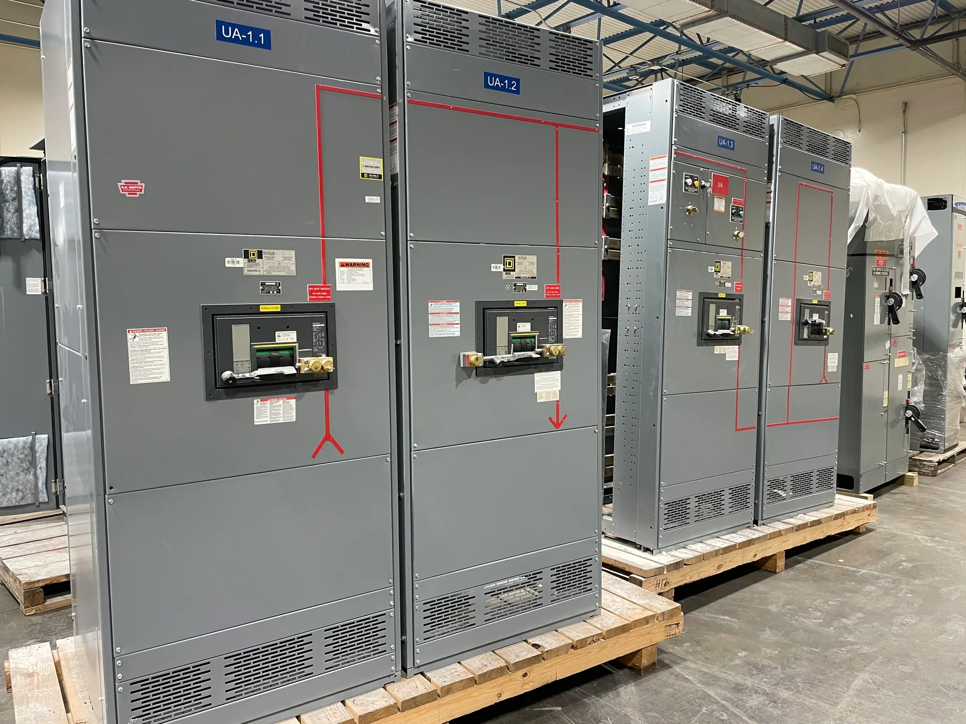
Indoor electrical room distribution works best when the equipment envelope is checked against the whole room—not just the wall space available for a lineup. Plan for working clearances, heat removal, door and corridor dimensions, cable routing, and the path needed to place or replace equipment. These constraints can affect lineup configuration and project scope, so confirm them against applicable requirements, site conditions, and the proposed equipment drawings. Switchgear Builder Virginia manufactures custom new switchgear in the USA using all-American components and ships nationwide. Equipment configuration, ratings, schedule, and any applicable approvals require review and verification for the project.
Room and working space
Start with a measured room plan that shows the equipment footprint, doors, columns, finished surfaces, and other fixed obstructions. Then compare the proposed lineup with the space needed to operate, inspect, and maintain it. Required working clearances depend on the installation and applicable requirements; have the project’s qualified electrical and design professionals confirm them rather than relying on a generic diagram. Check front access and any specified rear or side access, along with the distance between opposing equipment faces. Also account for doors that swing into the room and equipment projections such as handles or open doors. If the available space is tight, compare alternate lineup lengths, depths, and section arrangements before the room is finalized. A custom build may help address a constrained layout, but it does not remove clearance or access requirements. Verify the arrangement against project drawings before release.
Heat and ventilation
Electrical equipment produces heat in operation, so room ventilation and cooling should be considered alongside the lineup layout. Ask the design team to evaluate anticipated equipment losses, room conditions, and the ventilation or cooling strategy appropriate to the application. Do not assume that an existing fan, louver, or air-conditioning system will be adequate for a changed load or a replacement lineup. Confirm that the proposed equipment’s environmental limits and installation requirements fit the room, and identify how airflow paths may be affected by partitions, cable trays, or nearby equipment. Dust, moisture, and other environmental exposures may also influence equipment selection and enclosure requirements; verify these conditions with the design team and manufacturer. The heat-management approach is project-specific, not a substitute for required clearances or maintenance access. Resolve open questions before finalizing dimensions, so room changes and equipment details can be coordinated rather than discovered during installation.
Doors and delivery path
The equipment must fit through the route to its final position, not merely within the electrical room. Measure clear door openings, corridor widths, ceiling height, turns, thresholds, and any temporary obstructions along the delivery path. Compare those dimensions with the proposed shipping configuration and largest individual section; do not assume the assembled lineup can be moved as one piece or that it can be divided in the field. Confirm handling and placement needs with the project team and manufacturer, including access for suitable moving equipment where required. Building access restrictions, elevator limits, and scheduled construction work may affect the plan, so verify them for the actual site. If an opening is too small, discuss feasible equipment sectioning or construction sequencing before drawings are approved. Nationwide shipping does not establish site access or installation arrangements. Coordinate those responsibilities separately, and confirm the final route and dimensions before equipment is released for manufacture.
Replacement access
For replacement projects, document both the existing equipment footprint and the route for removing it and bringing in the new lineup. Existing dimensions can be incomplete or affected by later renovations, so verify critical measurements at the site when access permits. Note obstructions, cable entry locations, wall openings, floor conditions, and any construction that might need alteration. Compare the new equipment envelope with the available working space and the route through the building; a lineup that fits the room may still be impossible to move through the doorway. Also coordinate the proposed configuration with the electrical design, connection points, and planned outage sequence. Do not treat an existing arrangement as proof that current requirements are satisfied. Have qualified project professionals review code, utility, and operational considerations applicable to the specific installation. Early verification can reveal whether the project needs a revised lineup arrangement or building work before procurement and construction schedules are set.
Configuration and verification
Turn the room survey into a coordinated drawing package showing dimensions, working space, access route, cable entry, and relevant environmental conditions. Identify which dimensions are verified and which remain assumptions, then close gaps before approving the equipment layout. For applicable low-voltage switchboards, UL 891 assemblies may be specified; confirm whether that requirement applies to the project and verify the proposed assembly documentation. Do not apply that standard to medium- or high-voltage equipment. Ratings, construction details, approvals, and schedule are subject to project review and quote, not inferred from a room sketch or general product description. Switchgear Builder Virginia can manufacture custom new switchgear in the USA with all-American components and ship nationwide. The appropriate configuration depends on verified project requirements, available space, and the final design. Keep the room, equipment, and delivery-path drawings aligned through review so changes are identified before they affect manufacture or site preparation.