
APPLICATIONS / MANUFACTURER DIRECT
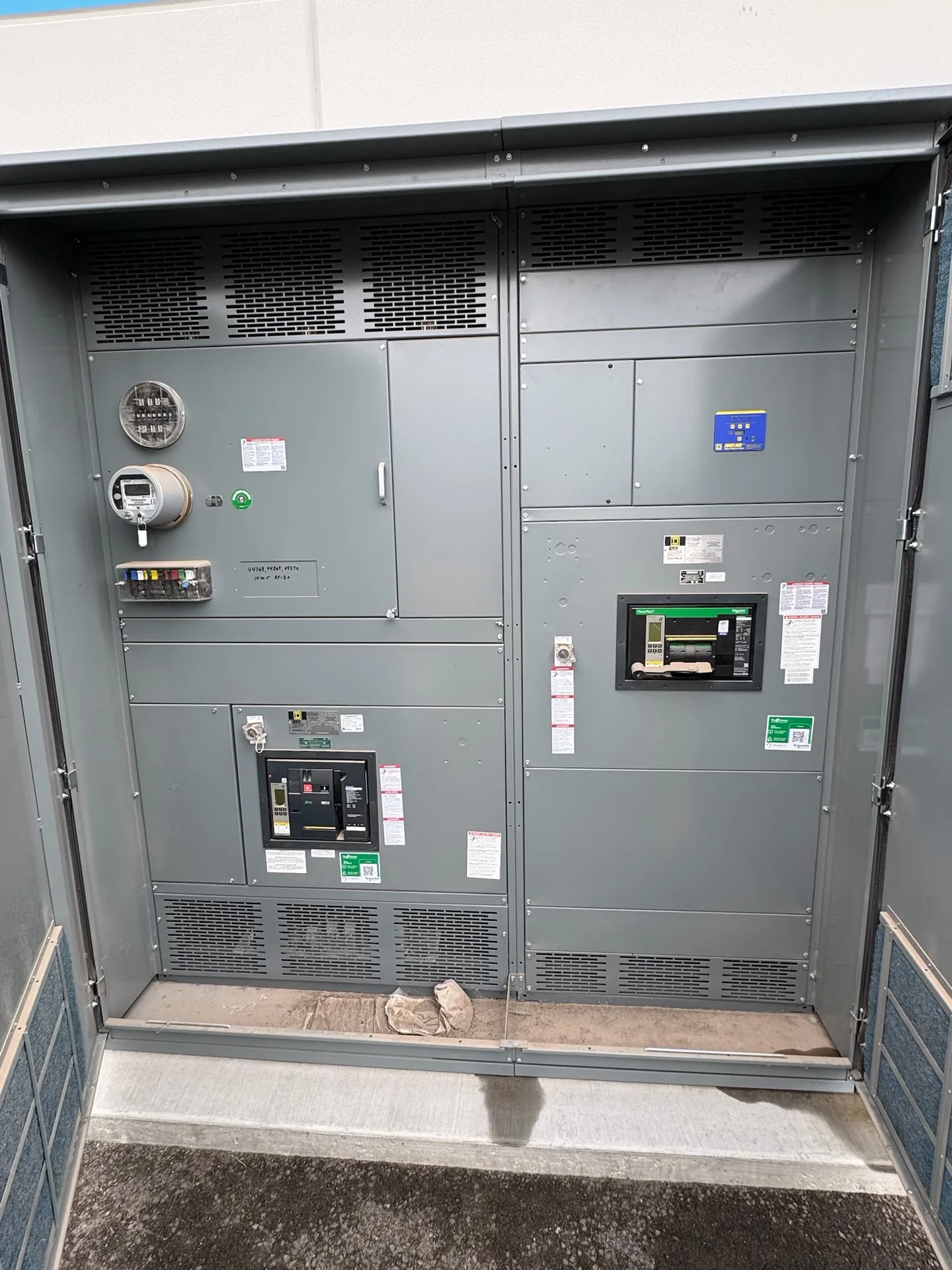
Main-tie-main distribution uses two main devices and a bus tie to connect sections of a facility’s electrical system. The arrangement can support different operating states, but the tie’s position alone does not establish that a transfer is safe or that connected equipment can carry the changed load. Buyers should define normal and abnormal states, interlocks, available fault current, and transfer limits before selecting an assembly. Switchgear Builder Virginia manufactures custom new switchgear in the USA using all-American components. Configuration, ratings, schedules, and applicable approvals require project-specific review and verification.
Define Operating States
Start with a one-line diagram that identifies each source, main device, bus section, tie breaker, and significant load group. Then state which devices are normally open or closed and what conditions permit a change. A common arrangement keeps the tie open during normal operation, with each source feeding its own bus section; other operating philosophies may differ. Do not assume that a familiar “open-transition” or “closed-transition” label fully describes the intended sequence. Document whether transfer is manual or automatic, what initiates it, what confirms the alternate source is acceptable, and what conditions block transfer. For abnormal cases, consider source loss, a bus fault, maintenance isolation, and restoration after an outage. These are design scenarios to evaluate, not promises that every configuration can serve every load without interruption.
Specify Interlocks
Interlocks help prevent prohibited device combinations, but their exact logic must follow the approved operating sequence and source characteristics. The design team should decide whether electrical, mechanical, key, or combined interlocking is appropriate, and identify the devices and control circuits involved. For example, if paralleling sources is not intended, the sequence should prevent the tie and both mains from being closed together under the defined operating conditions. That example is not a substitute for checking the actual sources, controls, and switching procedure. Specify how interlocks behave during loss of control power, device failure, or a discrepancy between indicated and actual position. Also clarify local and remote control authority, alarms, status indication, and any required permissives. Review the sequence with the facility’s electrical engineer and operations team before equipment details are finalized; verify any requested control or interlock features against the quoted design.
Check Fault Current
Available fault current must be evaluated for each relevant source and bus configuration, including states created when the tie is closed. A bus arrangement that changes source contribution can change the duty seen by breakers and other components. Provide current utility or source data, transformer information, conductor details, and any existing short-circuit study to the project team; assumptions should be identified rather than treated as confirmed values. The review should establish the required interrupting and withstand capabilities for the specified assembly and device arrangement. Do not infer those capabilities from a system voltage, breaker frame size, or a generic product description. Where an existing system is involved, confirm its present configuration and condition through qualified project review. Ratings and component selection are subject to the project documents, quote, and verification. For applicable low-voltage switchboards, UL 891 may be relevant; it does not apply to medium- or high-voltage switchgear.
Set Transfer Limits
A closed tie can shift load between sections, so check the expected load on each bus and source in every allowed state. Include starting or inrush loads, load growth assumptions, and equipment that cannot tolerate an interruption or brief voltage disturbance. Identify whether the operating plan allows staged transfer, requires load shedding, or limits which loads may move. Confirm source capacity, protective-device coordination, and conductor and bus ratings for the contemplated condition rather than relying only on normal operating totals. If one source is unavailable, the remaining source may not have capacity for the entire facility; the operating plan should make that constraint explicit. Transfer timing and continuity depend on the system, control scheme, and connected loads, so avoid treating a tie arrangement as an automatic backup solution. Record operating restrictions in a form maintainers can use.
Prepare the Project Scope
A useful inquiry package includes the one-line diagram, voltage and frequency, source details, fault-current information or study status, load data, operating-state table, and desired control sequence. Note the installation environment, physical constraints, connection requirements, and any interfaces to existing equipment; each requires confirmation during engineering review. Identify whether the project calls for a new lineup, a defined interface with an existing system, or other scope, without assuming compatibility from a drawing alone. State applicable specifications and required documentation, inspections, tests, or approvals so their availability and responsibility can be verified before commitment. Switchgear Builder Virginia can review requirements for custom new switchgear manufactured in the USA with all-American components and nationwide shipping. Lead times and ratings are confirmed by quote and project verification, not assumed from the topic or location. The final scope should resolve open technical decisions before release.