
APPLICATIONS / MANUFACTURER DIRECT
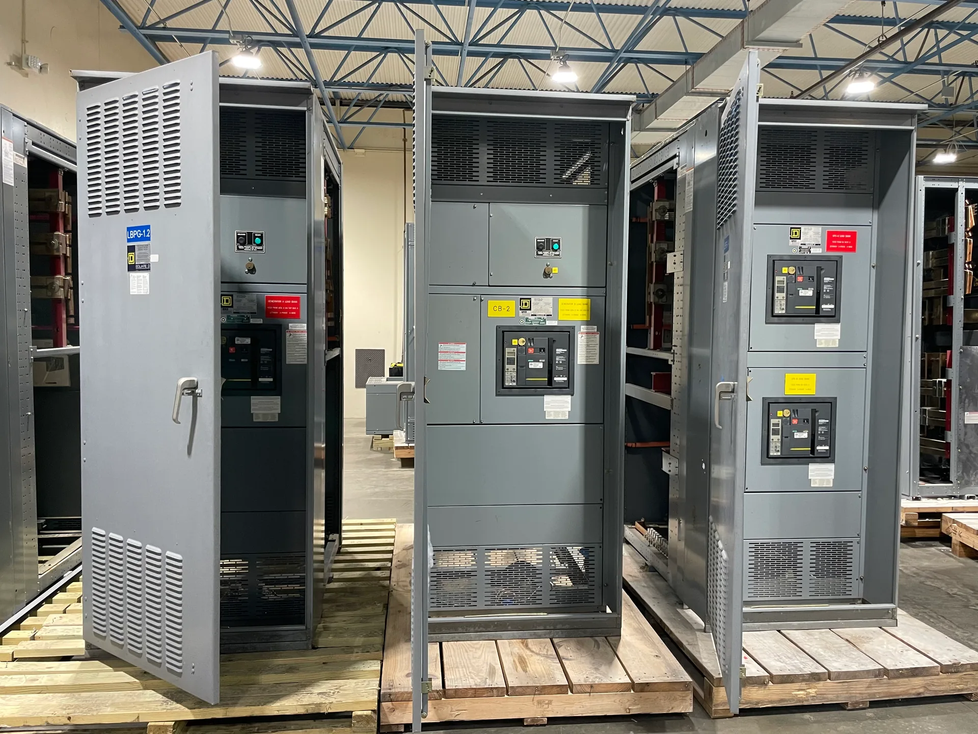
Selective coordination helps keep an electrical fault from shutting down more of a facility than necessary. It matters where continuity is important, such as emergency systems, critical process loads, or buildings with distinct distribution zones. The right approach depends on the complete protective-device arrangement, available fault current, equipment configuration, and operating modes—not a switchboard label alone. Switchgear Builder Virginia can custom-build new switchgear for project requirements, with all-American components, direct USA manufacturing, and nationwide shipping. Lead times and equipment details are subject to quotation and verification. A project-specific coordination study should establish the required device relationships before equipment is specified; proposed settings and configurations must be checked against the final design and applicable project requirements.
Where coordination matters
Selective coordination is often considered when an electrical fault should disconnect the smallest practical portion of a system while other loads remain energized. A project team may evaluate it for emergency or legally required power systems, healthcare facilities, data and communications spaces, industrial processes, or large buildings with separately served areas. These are application examples, not a claim that one arrangement is suitable for every facility or that a particular code rule applies. The designer should identify which loads need continuity, which sources supply them, and what level of interruption is acceptable. Then the project can establish the required boundaries between protective devices. A switchboard is one part of that system; upstream utility or generator protection, downstream panels, transformers, and transfer equipment may also affect the result.
Map the complete path
Start by documenting each source and the path from it to the loads under consideration. Include upstream overcurrent devices, switchgear and switchboards, feeder breakers or fuses, transformers, transfer equipment, and downstream distribution devices where applicable. Record manufacturer and device identification, frame or fuse type, trip-unit details, available settings, and relevant time-current information when available. Also capture conductor and transformer data needed by the study engineer. Missing or assumed device information can make a coordination conclusion unreliable, so identify gaps rather than treating them as confirmed. A one-line diagram is useful, but it should match the intended equipment and be supported by current schedules and submittals. For new equipment, communicate required device relationships and interfaces early so the proposed configuration can be reviewed against the complete distribution path.
Account for operating modes
A system may operate differently on normal utility power, generator power, alternate feeds, or through transfer equipment. Each mode can change the available fault current and which protective devices are in the active path. Document intended source combinations, transfer sequences, tie-breaker positions, and any normally open connections that could be closed during operation. Include emergency or standby sources if they are part of the design. The study engineer can then evaluate each relevant configuration rather than relying on a single normal-operation case. Do not assume that settings suitable for one source or topology remain appropriate in another. Where operating procedures or interlocks constrain system configurations, provide those design details for review. Any final device settings, equipment selection, and operating restrictions should be confirmed through the project’s engineering process and reflected in approved documents.
Study before specifying
Selective coordination is a system-level engineering determination, not a feature that can be promised from a product description. Require a project-specific study using verified protective-device data and applicable fault-current information. The engineer should define the study scope, operating cases, coordination criteria, and any limitations that need to appear in project documents. Review time-current curves and device data together, while recognizing that the final assessment depends on the study method and the governing project requirements. If the analysis identifies conflicts, options may include revisiting device types, settings, system arrangement, or the desired continuity objective; each change can affect cost, space, protection, and operations. Resolve decisions with the responsible design professionals before release for manufacture. A quote can address specified equipment needs, but it does not replace the study or verify coordination by itself.
Build to verified requirements
Once the design team has established the requirements, provide the switchgear manufacturer with the approved one-line diagram, device schedule, source and operating-mode information, interface requirements, and relevant study conclusions. Identify which details are fixed and which remain subject to engineering review. Switchgear Builder Virginia manufactures new custom switchgear in the USA using all-American components and ships nationwide; specific configurations, ratings, schedules, and lead times require quotation and verification. For applicable low-voltage switchboards, UL 891 assemblies may be considered where the project calls for them, with applicability and details confirmed for the equipment being quoted. Coordinate submittal review with the engineer and other project stakeholders, and verify that final documents reflect accepted selections. This approach keeps equipment decisions tied to the documented system design without implying a coordination outcome that has not been studied and confirmed.