
APPLICATIONS / MANUFACTURER DIRECT
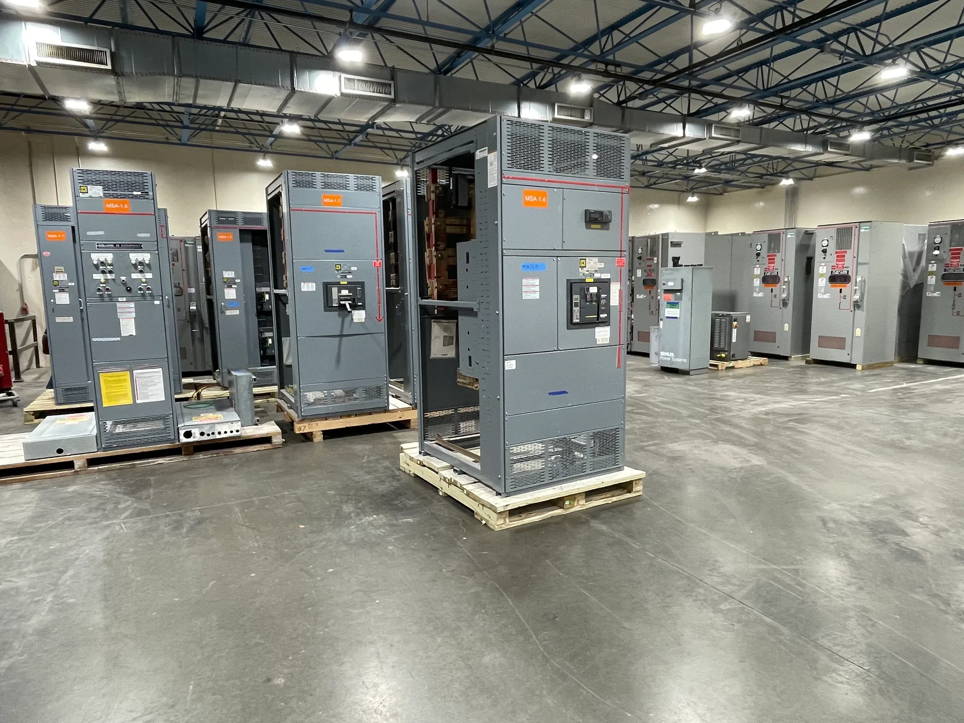
Transformer secondary distribution begins where the transformer’s low-voltage terminals meet the conductors and equipment serving downstream loads. The switchboard interface must be coordinated around the transformer’s actual secondary voltage, rated current, connection, available fault current, and installation conditions—not inferred from a nominal system description alone. Switchgear Builder Virginia manufactures new, custom switchboards in the USA using all-American components, with nationwide shipping and short lead times subject to project review and quotation. For applicable low-voltage switchboards, UL 891 assemblies can be specified where appropriate. The useful first step is to assemble verified transformer and system data so the equipment design can be evaluated against the intended distribution arrangement.
Start With Transformer Data
Provide the transformer nameplate information, including secondary voltage, phase, frequency, kVA rating, impedance, and winding connection, when available. Confirm whether the secondary is grounded and identify the intended grounding arrangement; do not assume these details from the building’s service voltage. These inputs affect how the switchboard is configured, how conductors connect, and what protective-device requirements need review. Transformer impedance is relevant to estimating available fault current, but it is not enough by itself to establish the final value at the switchboard. The calculation may also depend on the upstream system, transformer configuration, conductor length and impedance, and other connected sources. If the transformer has not been selected, identify the design assumptions clearly and have them verified before equipment release. Switchgear Builder Virginia can use the project information to develop a custom new switchboard scope, with ratings and configuration subject to quotation and engineering review.
Verify Current and Fault Duty
The transformer’s secondary full-load current is a starting point for sizing the distribution arrangement, not a complete equipment selection. Loads, demand assumptions, future capacity, parallel sources, and applicable design requirements can influence the bus, feeder, and main-device decisions. Have the responsible design professional establish the calculated load and available fault current at the proposed switchboard location. That fault-current value helps determine whether the specified equipment and protective devices are suitable for the system; do not treat transformer impedance or a generic kVA chart as a substitute for a project calculation. Coordinate the equipment short-circuit ratings and protective-device capabilities with the documented system conditions. Where utility or upstream information is pending, state the assumption and identify who will confirm it and when. The final quoted configuration and ratings require verification against complete project data. This disciplined approach avoids designing to an unsupported fault-duty assumption that may later affect selection, coordination, or installation.
Coordinate Conductors and Terminations
Document the secondary conductor material, quantity, size, insulation, routing, and termination approach before finalizing the switchboard interface. The transformer lugs, switchboard terminals, cable bending space, raceway entry, and available working clearances must be considered together; a conductor that appears adequate electrically may still create a difficult physical connection. Confirm whether conductors enter from above, below, or another direction, and identify any site constraints that could affect enclosure placement or cable routing. The specified conductor ampacity and termination temperature assumptions should be reviewed by the responsible electrical designer against applicable requirements and the selected equipment. Do not assume a terminal accepts a particular conductor range or multiple conductors unless the equipment documentation confirms it. A custom switchboard layout can address project-specific connection needs, but available space, terminal provisions, and ratings remain subject to design review and quotation. Provide drawings or clear connection notes early to reduce avoidable interface changes.
Plan Protection and Switching
Define the intended protection arrangement, including whether the secondary distribution uses a main protective device, feeder devices, or another documented scheme. The choice depends on system design, load distribution, fault-current information, coordination objectives, and applicable project requirements; it should not be selected from a generic template alone. Identify the loads or downstream panels served by each feeder and provide anticipated ratings where established. Protective-device type, trip settings, interrupting capability, and coordination with upstream or downstream devices require review by qualified project professionals using verified system data. Also clarify whether the switchboard needs metering, controls, or other specified accessories, since those options can affect layout and wiring. Switchgear Builder Virginia can manufacture new custom equipment to the approved project requirements, but no unverified feature or rating should be assumed from a brief description. For applicable low-voltage switchboards, UL 891 construction may be specified where appropriate; applicability and exact configuration must be confirmed for the project.
Prepare the Interface Package
A coordinated submittal package should identify the transformer, secondary system, calculated fault current at the equipment, load and feeder schedule, conductor plan, protection requirements, and intended installation conditions. Include available one-line diagrams, transformer data, physical connection details, and project specifications, while marking unresolved items as pending rather than treating them as confirmed. Review equipment dimensions and connection points with the parties responsible for the transformer, conductors, and installation before approval. This helps surface mismatches such as an unsuitable cable-entry direction or incomplete fault-duty information while changes can still be evaluated. Switchgear Builder Virginia provides direct USA manufacturing, all-American components, custom builds, and nationwide shipping. Lead times and ratings are subject to quote and verification; no schedule should be treated as committed until confirmed for the specific order. The final design should follow the approved project documents and applicable review process, with equipment details established from verified requirements rather than assumptions.