
APPLICATIONS / MANUFACTURER DIRECT
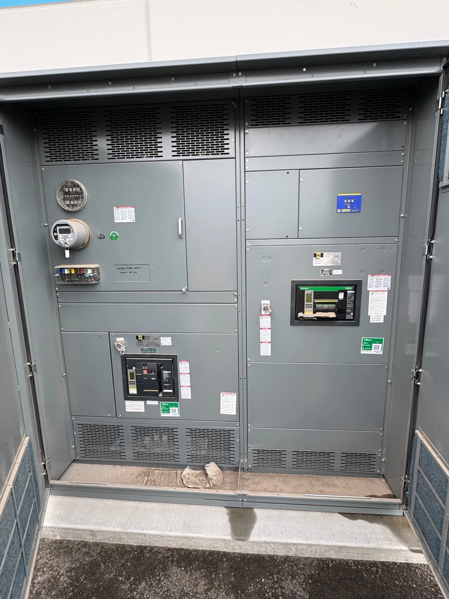
Parallel transformer distribution uses two or more transformer sources to serve a common load system, but the arrangement must be engineered around the intended operating modes. Impedance, bus configuration, fault duty and interlocks all affect whether sources may operate together or separately. Switchgear Builder Virginia manufactures custom new switchgear in the USA using all-American components, with nationwide shipping and short lead times subject to project scope and quote. The engineer of record should define system requirements, and equipment ratings, schedules and applicable approvals must be verified for each project.
Define the Operating Modes
Start by documenting how the distribution system is expected to operate: transformers in parallel, one transformer carrying the full load, a split-bus arrangement, or a planned transfer between sources. The intended sequence matters because equipment that is suitable for one mode may not suit another. Identify normal and abnormal configurations, including maintenance conditions and the response to loss of a transformer or source. Confirm whether paralleling is continuous, occasional, or prohibited, and who is authorized to change the lineup state. These decisions guide the one-line diagram, bus arrangement, protective-device coordination and interlock scheme. The engineer should also establish the load assumptions for each mode, including future additions where relevant. Clear operating requirements help the switchgear manufacturer develop a buildable design without treating a nominal transformer count as proof that every transformer may be connected to the same bus.
Compare Transformer Impedance
Transformer impedance affects how load and fault current are shared when units operate in parallel. For reasonably balanced sharing, the engineer evaluates impedance values and other transformer characteristics together, rather than relying on a single nameplate figure. Differences can cause one unit to carry a disproportionate share of load, potentially limiting usable capacity or affecting protection. Confirm each transformer’s voltage ratio, phase relationship, impedance data, capacity and connection details from the project documents and equipment information. Any acceptance limits should come from the responsible engineer, not an assumed universal tolerance. If a transformer may be replaced or added later, define how its characteristics will be checked against the existing parallel group. Switchgear design can accommodate specified sources and operating modes, but it cannot make mismatched transformer behavior disappear. Treat transformer compatibility as an upstream design decision that must be resolved before final equipment ratings and configuration are approved.
Choose the Secondary Bus Arrangement
The secondary bus arrangement should reflect how the facility needs to distribute loads and isolate equipment. A common bus can provide a shared distribution point, while a bus divided into sections may allow selected loads to remain separated or support a defined transfer sequence. The right choice depends on load criticality, available transformer capacity, maintenance objectives, physical layout and the operating modes approved by the engineer. Identify which breakers connect transformer secondaries to the bus, which devices tie bus sections together, and whether any loads require dedicated feeders or separation. Also establish whether the tie is normally open or normally closed; that choice affects operating logic and the configurations that must be evaluated. For low-voltage switchboard applications, a UL 891 assembly may be applicable, subject to project scope and verification. Bus ratings, compartment arrangement and device selection remain specific to the approved design and quote.
Evaluate Fault Duty and Protection
When transformer secondaries are connected in parallel, available fault current can differ from the value expected with a single source. The engineer should evaluate the applicable source combinations, transformer data, impedance, conductor characteristics and system configuration to establish the required fault-duty basis. Check the resulting requirements against the proposed switchgear and protective devices, including the conditions for a bus tie closed or open when those modes are permitted. Protection coordination must be considered alongside equipment ratings so that a fault response aligns with the system design. Do not assume that a rating suitable for one transformer arrangement automatically remains suitable after sources are paralleled. The project documents should state the required ratings and any assumptions used to calculate them. Switchgear Builder Virginia can build to verified project requirements; final ratings, device selections and any applicable assembly approvals are confirmed through engineering review and quotation, not inferred from this topic alone.
Specify Interlocks and Verification
Interlocks help prevent operating sequences that the system design does not permit, such as closing a bus tie under a prohibited source condition. The engineer should define the allowed and blocked states, the devices involved, and whether the logic is mechanical, electrical or a combination suited to the specified equipment. Consider normal operation, loss of source, restoration, maintenance and any manual steps in the approved sequence. Document how operators can tell which sources and ties are connected, and ensure control power and status indications are addressed where required. Interlocks do not replace operating procedures, protection studies or qualified review. Before release, reconcile the one-line diagram, device schedule, control logic, transformer information and required ratings; resolve conflicts rather than leaving assumptions for fabrication. Switchgear Builder Virginia offers custom new builds, USA manufacturing, all-American components and nationwide shipping. Lead time and configuration are subject to scope, quotation and verification.