
GLOSSARY / MANUFACTURER DIRECT
A switchgear cell is a defined space or position within an equipment lineup, arranged for a particular device or function. The term is used differently across equipment types and designs, so it does not by itself specify dimensions, contents, or capabilities. For a new lineup, understanding how each cell is intended to work helps buyers discuss equipment arrangement, connections, access, and coordination before design details are finalized.
What a Cell Means
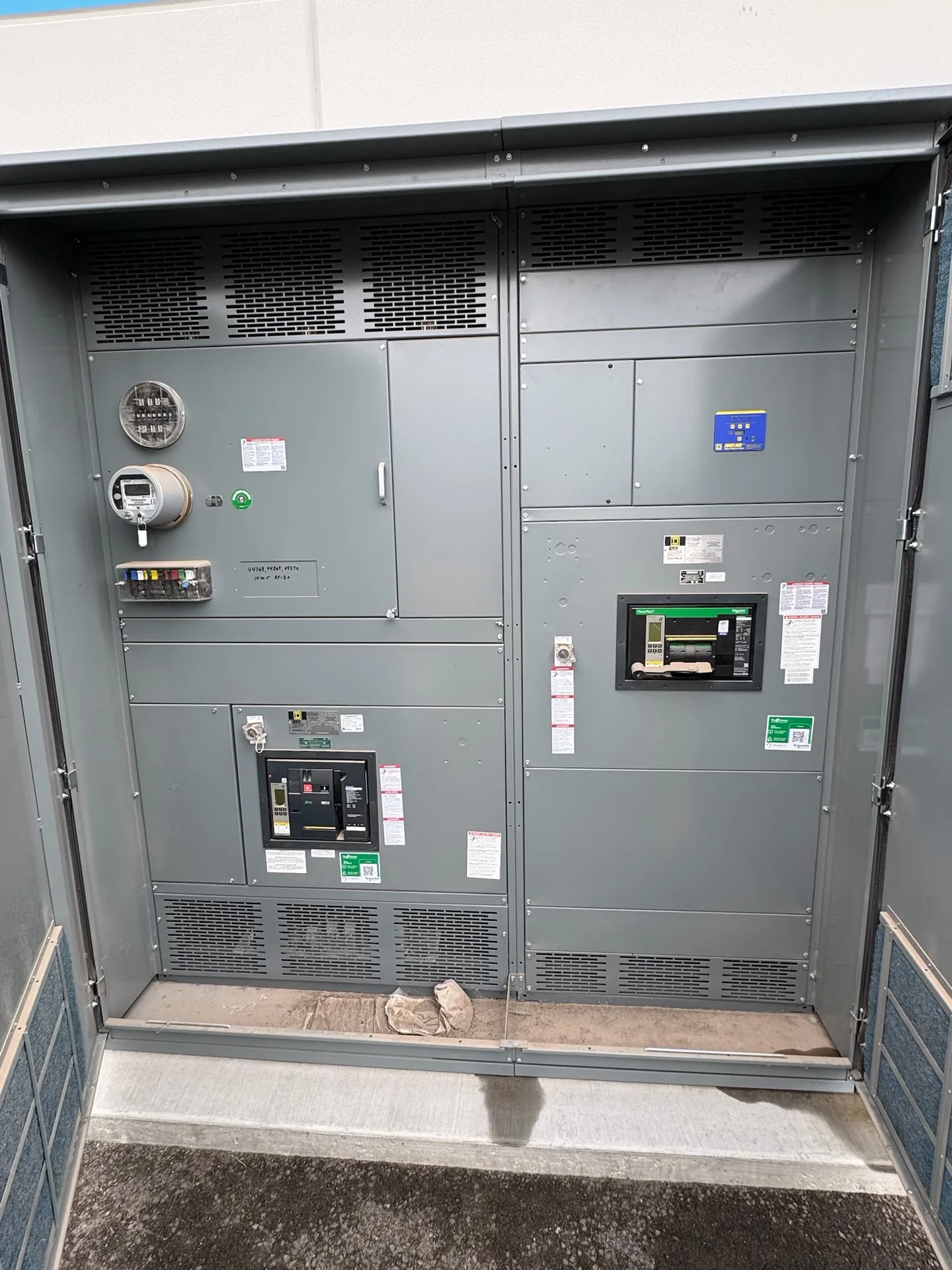
In practical terms, a switchgear cell is a compartment or designated position within a lineup for a device or function. Depending on the equipment and design, it may be associated with a circuit breaker, switching device, metering, control components, or another specified purpose. Some manufacturers and project documents use “cell” to mean a physical compartment; others use it more broadly for a lineup position or functional unit. The word alone does not tell you whether the space is enclosed, what equipment it contains, or how it is separated from adjacent sections. Buyers should check the equipment drawings and definitions used in the project specifications. A clear description connects the cell to its intended device, electrical function, and location in the lineup, rather than relying on the term as if it were a complete technical rating or construction standard.
Cell, Section, and Compartment
A lineup is the complete group of connected equipment arranged as a coordinated assembly. Within it, a section may describe a major vertical or functional part, while a compartment usually means a bounded space that separates equipment or wiring. A cell can refer to a compartment, a device position, or a functional unit, depending on the product vocabulary and drawings. These words are related, but they are not reliably interchangeable across all switchgear. For example, a drawing may show one section containing multiple functional spaces, or a device position whose boundaries are not described as a separate cell. When reviewing a quote or layout, ask which term the supplier is using and what physical area it identifies. Confirm how the identified space relates to adjoining sections, the lineup footprint, and the equipment assigned to it.
Interfaces and Interlocks
A cell’s interfaces are the physical and electrical connections or coordination points between its assigned device and the rest of the lineup. Depending on the design, these may involve bus connections, control wiring, secondary connectors, cable terminations, mounting arrangements, or connections to adjacent equipment. Their location and arrangement must be confirmed from project-specific drawings; the word “cell” does not define them. Interlocks are also design-specific. Where specified, they may coordinate equipment positions or operating conditions to restrict certain actions, but their presence, purpose, and implementation cannot be assumed from a cell label. Buyers should identify which devices need to interact, what control or interlocking functions the project requires, and which details need review by the responsible design team. Ask for the applicable drawings and documentation to show the proposed arrangement and interfaces before the equipment configuration is finalized.
Questions for the Project
When discussing a cell with a manufacturer, start with the lineup’s intended function and the device or components assigned to that position. Then clarify its location, required connections, control wiring, access needs, and relationship to neighboring equipment. Confirm which drawings identify the cell boundaries and interfaces, and whether the project uses “cell,” “section,” and “compartment” consistently. If the design calls for interlocks, specify the intended operating relationship rather than assuming a standard arrangement. Also verify equipment type, ratings, environmental requirements, and applicable project specifications separately; a cell name does not establish any of these. For replacement planning, existing dimensions and connection locations may matter, but they should be documented and evaluated for the proposed new equipment. A well-defined scope reduces ambiguity in layout review and helps all parties work from the same configuration.
New Lineup Planning
For a new switchgear project, cell arrangement is one part of the overall equipment design. The selected layout may affect how devices and wiring are grouped, where connections land, how the lineup fits the available space, and what access the project requires. Those details depend on the equipment type, specifications, and site conditions, so they should be reviewed rather than inferred from a general glossary definition. Switchgear Builder Virginia manufactures new switchgear in the USA using all-American components and can develop custom builds; lead times and schedules are subject to quote and verification. Nationwide shipping is available. Before an order is placed, confirm the proposed cell functions, interfaces, interlocks if required, and ratings against approved project requirements. The term helps organize a conversation, but the drawings and verified specifications define what the supplied lineup is designed to include.