
TECHNICAL GUIDES / MANUFACTURER DIRECT
An arc-flash study provider needs a documented picture of the electrical system, its equipment, and the protective devices that may clear a fault. A standard label, nameplate, or single fault-current value cannot establish the study result by itself. Gather current records for the system boundary being evaluated, flag missing information, and confirm assumptions with the study provider. These inputs help the provider model the system and identify where field verification may be needed before conclusions are issued.
System One-Line
Start with the latest available one-line diagram showing the electrical path from the serving source through transformers, switchgear, switchboards, panelboards, and other equipment in the study boundary. Include normal and alternate sources, tie breakers, generators, and operating configurations that could change the path or available fault current. Identify equipment tags, nominal voltages, transformer connections, and the points where protective devices separate sections. A drawing that omits a tie or alternate source can lead the provider to model a different configuration than the one intended. Mark known revisions and distinguish verified information from assumptions; do not silently treat an old drawing as current. If no complete one-line exists, provide the best records available and ask the study provider what field data or engineering work is needed to establish the model.
Source Fault Data
Request source information from the serving utility or other source owner through the appropriate project contact. The study provider may need available short-circuit current at the service point, source voltage, and any stated X/R information, along with the date and conditions behind the data. For a generator or other onsite source, provide equipment documentation and operating information requested by the provider. Transformer records should include nameplate data such as kVA, primary and secondary voltages, impedance, and winding connection when available. Identify multiple sources and operating modes rather than combining their values yourself. Fault-current data is specific to a point and system condition; a number from a nearby project or old study is not a substitute for confirmed inputs. Let the provider decide whether source data is adequate and what assumptions, if any, are appropriate.
Conductors and Connections
For each connection represented in the model, gather conductor material, size, quantity per phase, insulation or cable type when documented, and approximate route length. Include relevant busway or bus information and note where the path changes, such as a transformer connection or a long feeder. Length and conductor characteristics affect impedance, so missing or guessed values can change modeled fault current and protective-device behavior. Provide drawings, cable schedules, installation records, or other reliable documentation that helps the provider trace the path. If records conflict or a segment cannot be identified, flag the gap instead of choosing the more convenient value. The study provider can determine whether additional site verification or a documented assumption is needed. These details support the model; they do not independently establish an arc-flash result or a safe work condition.
Equipment and Protective Devices
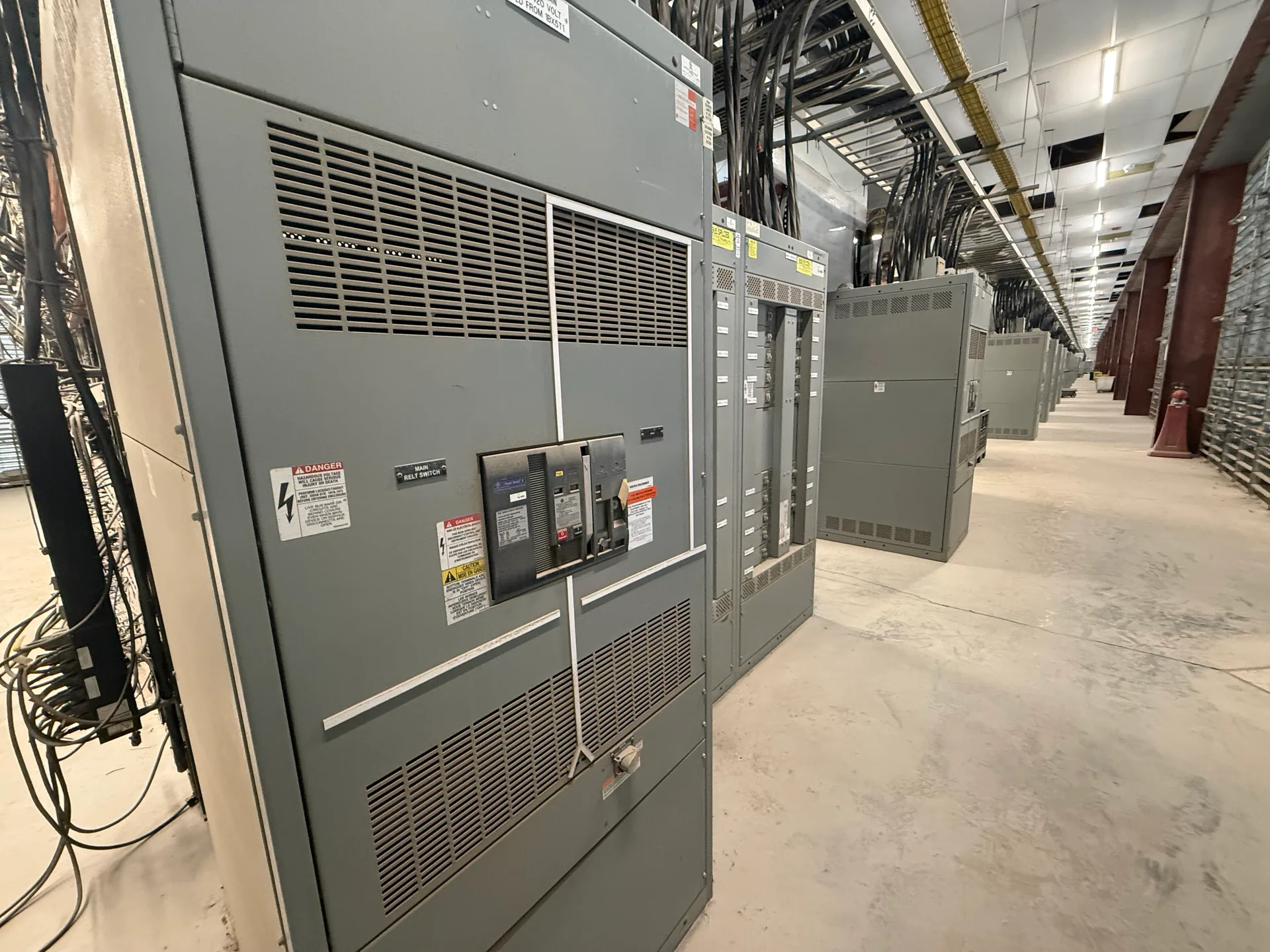
Collect equipment identification and nameplate information for the study boundary, including manufacturer and model where legible, voltage, and other details the provider requests. Record protective-device type, catalog or model number, sensor or trip-unit details, and current settings, including long-time, short-time, instantaneous, and ground-fault functions when present. Include fuse class and rating where applicable. Provide the latest available coordination study or settings records, but do not assume they match installed devices; note any uncertainty for provider review. Settings and device condition can affect modeled clearing time, so the study requires the actual configuration being evaluated, not a generic label or presumed standard setting. Do not operate equipment to gather information. Arrange any needed inspection or verification through qualified personnel under the site's safety procedures.
Review Gaps Before Modeling
Before sending the package, compare the one-line, equipment records, and settings list for mismatched tags, missing sections, unclear source configurations, or dates that suggest a possible change. Tell the study provider about known modifications and identify which inputs are confirmed, estimated, or unavailable. Ask what format and level of field verification the provider needs; the study provider determines the modeling method and evaluates the results. Switchgear Builder Virginia manufactures and supplies new switchgear, including custom builds, and can discuss equipment information relevant to a new-equipment project. Any proposed ratings, configurations, and schedule remain subject to quote and verification. For applicable low-voltage switchboards, UL 891 assemblies may be specified; that designation is not an arc-flash result and does not replace a study. Nationwide shipping is available, while project-specific equipment requirements should be confirmed for the application.