
TECHNICAL GUIDES / MANUFACTURER DIRECT
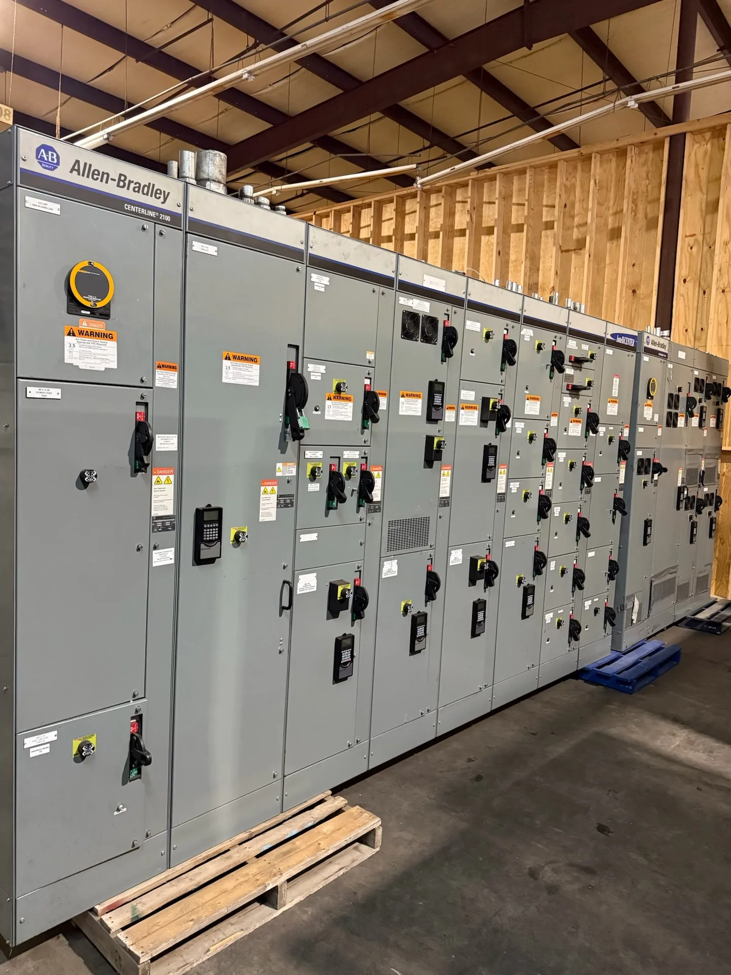
Ground-fault sensing is a measurement choice, not a stand-alone protection decision. Residual sensing and ground-return sensing detect imbalance in different ways, and each depends on how conductors and the neutral are arranged. For a new switchboard or switchgear project, the useful comparison starts with the system’s grounding method, intended protection zones, and coordination study—not with a sensor name alone. Switchgear Builder Virginia manufactures new custom equipment in the United States using all-American components, with nationwide shipping. Available configurations, schedules, and ratings are subject to project review and quote; confirm equipment suitability and applicable requirements with the project engineer.
Residual sensing
Residual sensing evaluates the combined current in the phase conductors and, where the system requires it, the neutral. Under normal conditions, current entering a monitored zone should balance current leaving it. A ground fault can create a difference that the sensing arrangement detects. The practical question is which conductors pass through the sensor and which current paths remain outside its measurement boundary. If a neutral is present but omitted where it should be included, ordinary neutral current may appear as an imbalance; including the wrong conductors can also obscure the intended signal. Residual arrangements can suit defined feeder or service zones, but the one-line diagram and grounding scheme determine the correct setup. Treat sensor placement, polarity, and protection settings as coordinated design details for review, not as universal field adjustments.
Ground-return sensing
Ground-return sensing measures current in a designated grounding or return path rather than summing the phase conductors at one sensing point. Its usefulness depends on the fault-current path actually passing through the monitored conductor and sensor. That path must be distinguished from neutral current and from parallel metal paths that could carry some fault current elsewhere. The engineer therefore needs to review bonding locations, grounding conductors, enclosure paths, and the boundaries of the protected zone. A return-path sensor may offer a clear measurement for a deliberately arranged system, but it does not automatically capture every possible current route. Project documents should identify the intended conductor, its routing, and the protective device associated with the signal. Verify the arrangement against equipment configuration and applicable design requirements before selecting components or settings.
Neutral configuration
Neutral treatment is often the key distinction between a workable sensing scheme and a misleading one. A solidly grounded system with a neutral, a separately derived source, or a service arrangement with multiple grounding or bonding points can present different current paths. Ask the design team to identify whether the neutral is switched, where bonding occurs, and which conductors belong inside each sensing zone. Those details affect how normal load current and fault current appear to the sensor. Do not infer the correct arrangement from a breaker label or a generic diagram: confirm it on the project one-line and equipment drawings. For custom switchgear, document the source, neutral path, grounding conductors, and intended sensing boundaries before the assembly is configured. The protection engineer should resolve ambiguities rather than relying on assumptions during installation.
Coordination and zones
Sensing method and protective coordination must be considered together. A detected ground fault may need to initiate an alarm, a trip, or another specified response, and the chosen response affects continuity of service and the protection zones. The engineer should review the available fault-current information, device characteristics, time-current coordination, and the consequences of a fault at each location. Upstream and downstream devices must be evaluated as a system; selecting a sensor alone does not establish selectivity or a suitable trip threshold. Confirm how the sensing signal reaches its protective device, what settings are required, and how those settings will be documented and verified. If a project calls for testing or acceptance checks, identify the scope and responsible parties in the project requirements. Do not treat a general sensing description as evidence of a tested or approved configuration.
Specify for the project
A useful equipment specification states the system voltage and grounding arrangement, source and neutral details, protected conductors, sensing method under consideration, protection zones, and intended alarm or trip response. Include the current one-line diagram and coordination requirements, then ask the protection engineer to resolve sensor location and conductor routing. For a new low-voltage switchboard, confirm whether a UL 891 assembly is applicable and required for the project; applicability and configuration must be verified rather than assumed. Switchgear Builder Virginia can review project requirements for a custom new assembly manufactured in the United States with all-American components. Available features, ratings, and schedules are subject to quote and verification, so provide complete drawings and requirements early. Nationwide shipping is available, but shipping coverage does not establish a delivery date or replace engineering review, installation planning, or commissioning responsibilities.