
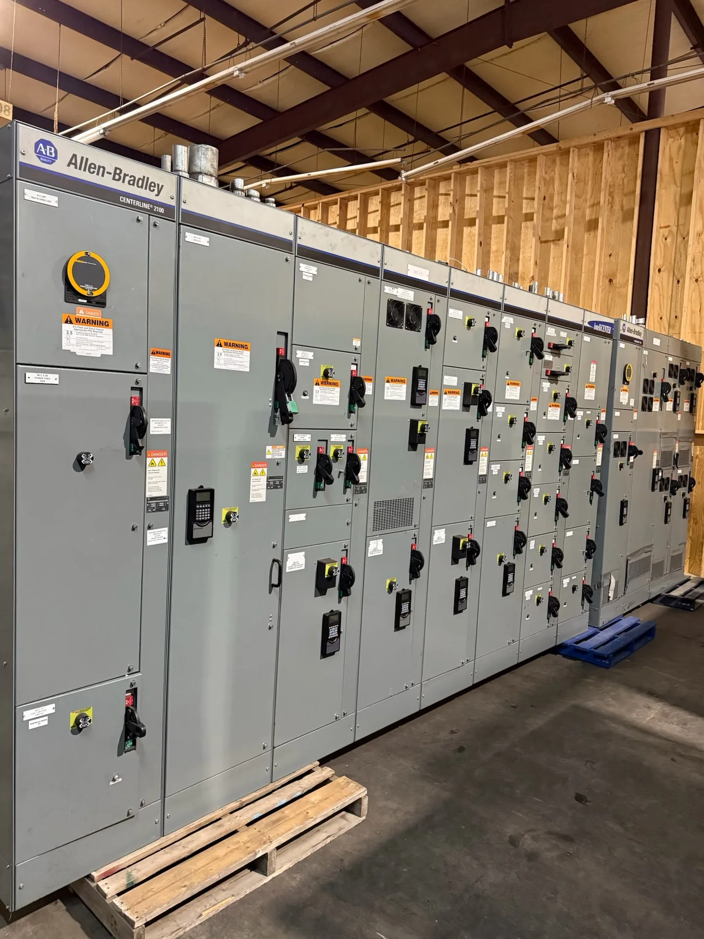
TECHNICAL GUIDES / MANUFACTURER DIRECT
Busbar bracing is the mechanical support that helps keep current-carrying conductors in position during a short circuit. Fault current can create powerful forces between and around bus bars, so assembly withstand depends on more than conductor size alone. Switchgear Builder Virginia builds new switchgear to project requirements, with custom configurations and all-American components. For a sound design, the project team must provide verified fault data and confirm how the complete assembly is evaluated. The considerations below explain what buyers should review when specifying bus support and fault withstand.

How Fault Forces Develop
During a short circuit, current flowing through nearby conductors creates magnetic forces that can push bus bars toward or away from one another. The force depends on the current magnitude and waveform, conductor spacing, and the physical arrangement of the bus. Higher available fault current can increase mechanical stress, but the peak first-cycle current may matter as much as the symmetrical RMS value. The system X/R ratio affects how large that initial peak can be. These forces act briefly, yet may bend conductors, strain joints, loosen supports, or transfer stress into the structure. The design question is therefore not simply whether a bar can carry normal load current. Buyers need to establish the fault conditions the assembly must withstand and evaluate the full bus-support arrangement against those conditions.
Start With Project Fault Data
A useful specification identifies the available short-circuit current at the equipment connection point, the system voltage, and the expected fault-clearing duration or protective-device clearing information. Where required by the design method, include X/R ratio or peak-current data, since asymmetry can increase the initial mechanical peak. Fault current can differ between service entrances, transformers, generators, and downstream locations, so a value from another point in the system may not apply. The engineer of record or qualified study provider should confirm the values and assumptions for the project. If utility data or the short-circuit study is preliminary, label it as such and resolve uncertainties before design release. Switchgear Builder Virginia can use confirmed project requirements to develop a custom new assembly; the final configuration and withstand capability must be reviewed against the applicable design basis and quote.
Support Spacing and Layout
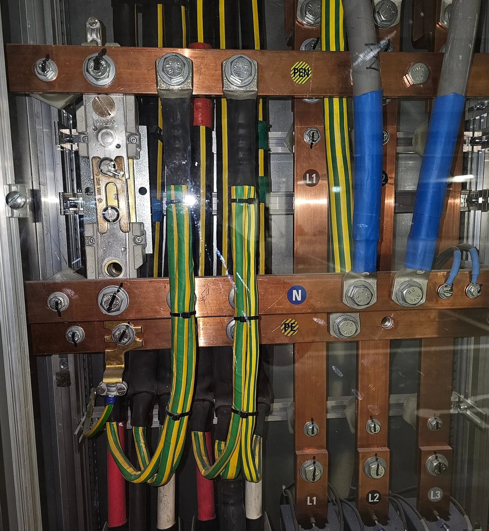
Bracing effectiveness depends on the entire mechanical arrangement: bus material and dimensions, phase spacing, orientation, support locations, joints, and how the assembly structure carries load. Shorter unsupported spans generally reduce conductor movement, but adding supports can affect clearances, accessibility, insulation layout, and assembly complexity. Changing a bus route or phase arrangement can also alter the forces, even if the ampacity remains unchanged. Buyers should avoid treating a support count or a single spacing dimension as proof of withstand. Instead, the design should document the bus geometry and support scheme used for its evaluation, including relevant connections and transitions. When project space is tight, compare layout options early; moving components later may change the bracing basis. Any proposed field modification should be reviewed by qualified project personnel and the manufacturer before it is treated as equivalent to the evaluated configuration.
Withstand Is an Assembly Question
Short-circuit withstand is a characteristic of the evaluated assembly, not just an isolated bus bar or support insulator. Forces can travel through joints, mounting points, barriers, and the enclosure, so a weak link elsewhere may govern. Buyers should distinguish a short-time withstand value from a peak withstand value and from a protective device’s interrupting rating; they describe related but different duties. Ask which current value, duration, peak basis, and configuration the documentation covers, and whether the specified incoming device or system conditions match that basis. Applicable product standards and evaluation methods depend on the equipment type and project. A catalog component rating by itself does not establish that a custom switchgear lineup has the same assembly withstand capability. Request supporting design or test documentation appropriate to the offered configuration, and confirm the scope with the responsible engineer before approval.
Review Before Release
Before releasing a purchase specification, align the fault study, one-line diagram, equipment layout, protective-device information, and required withstand criteria. Resolve changes in transformer size, utility contribution, generator operation, or system configuration that could raise available fault current or alter clearing time. Ask the manufacturer to identify assumptions, design limits, and any information still needed; do not infer an unlisted rating from a similar lineup. For a custom build, the approved drawings should show the relevant bus arrangement and interfaces so reviewers can check the design basis. If a project requires witnessed testing, a particular approval, or other documentation, state that requirement in the inquiry and verify its availability and scope before purchase. Switchgear Builder Virginia manufactures new equipment in the USA, uses all-American components, and ships nationwide; schedules and ratings remain subject to quote, project data, and verification.