
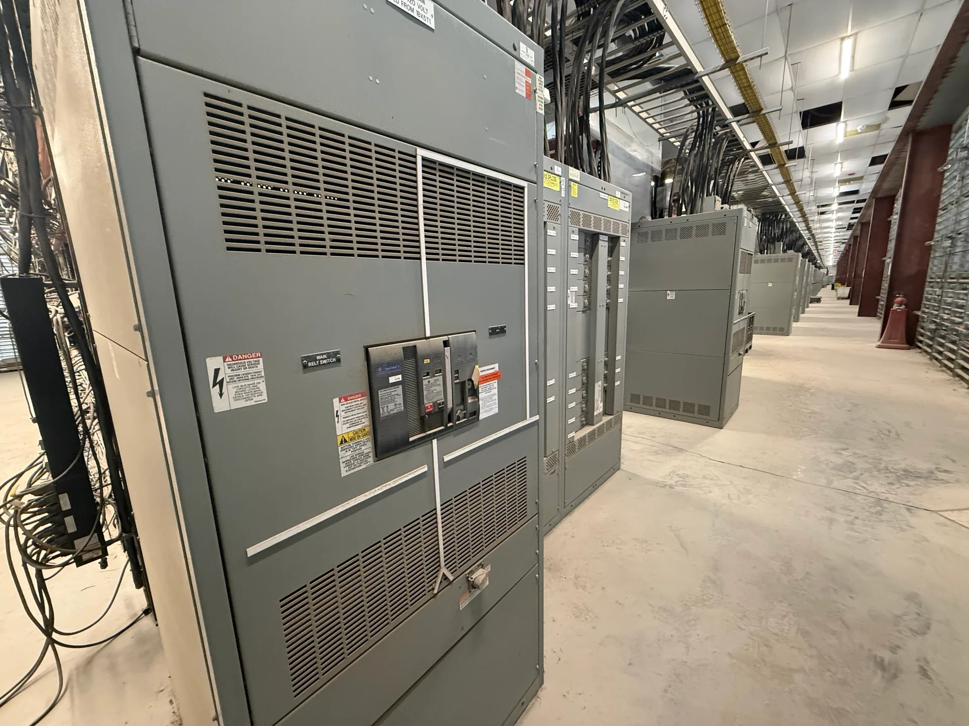
TECHNICAL GUIDES / MANUFACTURER DIRECT
Primary injection test planning starts with a clear question: which parts of the installed primary-current path and protection chain must the test demonstrate? The answer depends on the equipment, project documents, available test connections and the party responsible for commissioning. Switchgear Builder Virginia manufactures new custom switchgear and can help buyers identify design information that may support a defined test scope. Testing itself, acceptance criteria and field work should be assigned explicitly rather than assumed to be included with equipment supply. Use the plan to coordinate the manufacturer, electrical contractor, testing provider and owner before the equipment is energized.
Define the test objective
Primary injection drives current through a defined portion of the primary circuit, allowing the team to assess that path and, when included in scope, associated current sensors and protection response. It is not a universal check of every switchgear function. Start by naming the question each test must answer: continuity through a bus or breaker path, sensor response, relay input behavior, or a coordinated trip sequence. A test aimed at one outcome may not demonstrate another. For example, verifying a sensor’s response does not by itself establish that the complete protective scheme will operate as intended. Identify equipment boundaries, phases, compartments and devices involved, then state what evidence counts as acceptable. Switchgear Builder Virginia can discuss new custom switchgear design requirements with buyers; field-test methods and acceptance decisions belong to the project’s designated qualified testing and engineering parties.
Map the current path
Use current-path drawings and equipment documentation to show where injection begins and ends, which conductors and connections carry test current, and which devices are expected to respond. Confirm the arrangement for each phase and identify any shared or parallel paths that could affect what the readings demonstrate. The plan should account for the intended circuit configuration, test access, protective devices that may operate, and any temporary connections proposed by the responsible testing team. Do not assume a test connection or isolation point exists unless drawings and equipment details confirm it. A practical boundary diagram helps distinguish equipment included in the test from upstream or downstream components that remain outside it. If the proposed method cannot reach a required path or creates ambiguity about current distribution, resolve that design or scope issue before scheduling field work; do not improvise connections on energized equipment.
Set limits and criteria
Specify the planned test current, duration, measurement points and acceptance criteria only after the responsible engineer or testing provider reviews the equipment design and applicable project requirements. Test-source capability, circuit impedance, connection method, conductor heating, device settings and manufacturer limitations can affect a suitable plan; no single current or duration fits every assembly. Record expected observations, measurement tolerances and the basis for each limit. Distinguish a functional check from a rating verification: a test result at a selected current does not establish every withstand, interrupting or short-circuit rating. Likewise, numerical test values are not proof that equipment carries a particular listing or rating. If the project documents do not define a criterion, assign someone qualified to establish and approve one before testing. Treat unresolved limits as a coordination item, not as permission to select an arbitrary value in the field.
Include sensors deliberately
When current sensors are in scope, identify their type, location, ratio or configured scaling, polarity, secondary wiring and destination device from approved drawings and documentation. State whether the test is intended to confirm response at the sensor, verify the signal received by a relay or meter, or observe a broader protection action. These are different endpoints and may require different connections, records and acceptance criteria. Coordinate relay settings and logic with the engineer responsible for the protection scheme; do not infer correct performance from a current indication alone. The testing plan should also specify how secondary circuits and any temporary test arrangements are controlled and restored by qualified personnel. If sensor characteristics or wiring details are unavailable, pause that portion of scope until the project team resolves them. For a new custom assembly, buyers can identify required sensors, interfaces and documentation during design coordination with Switchgear Builder Virginia.
Assign work and records
Name who approves the procedure, provides the test equipment, establishes safe work boundaries, performs the testing, observes results and authorizes return to service. These responsibilities may sit with different parties; equipment supply alone should not be read as field commissioning or testing. The owner and project team should coordinate outages, access, site conditions, permits and any required utility or facility approvals as applicable. Work methods must follow the approved procedure and applicable safety requirements; this planning guide is not an instruction for live work. Require a report that identifies equipment and circuit boundaries, instruments, connection arrangement, test values, settings or configuration relevant to interpretation, measured results, exceptions and restoration status. Retain approved drawings and final records with project documentation. Switchgear Builder Virginia manufactures and supplies new switchgear in the United States using all-American components, with nationwide shipping; schedules and ratings require project-specific quote and verification.