
TECHNICAL GUIDES / MANUFACTURER DIRECT
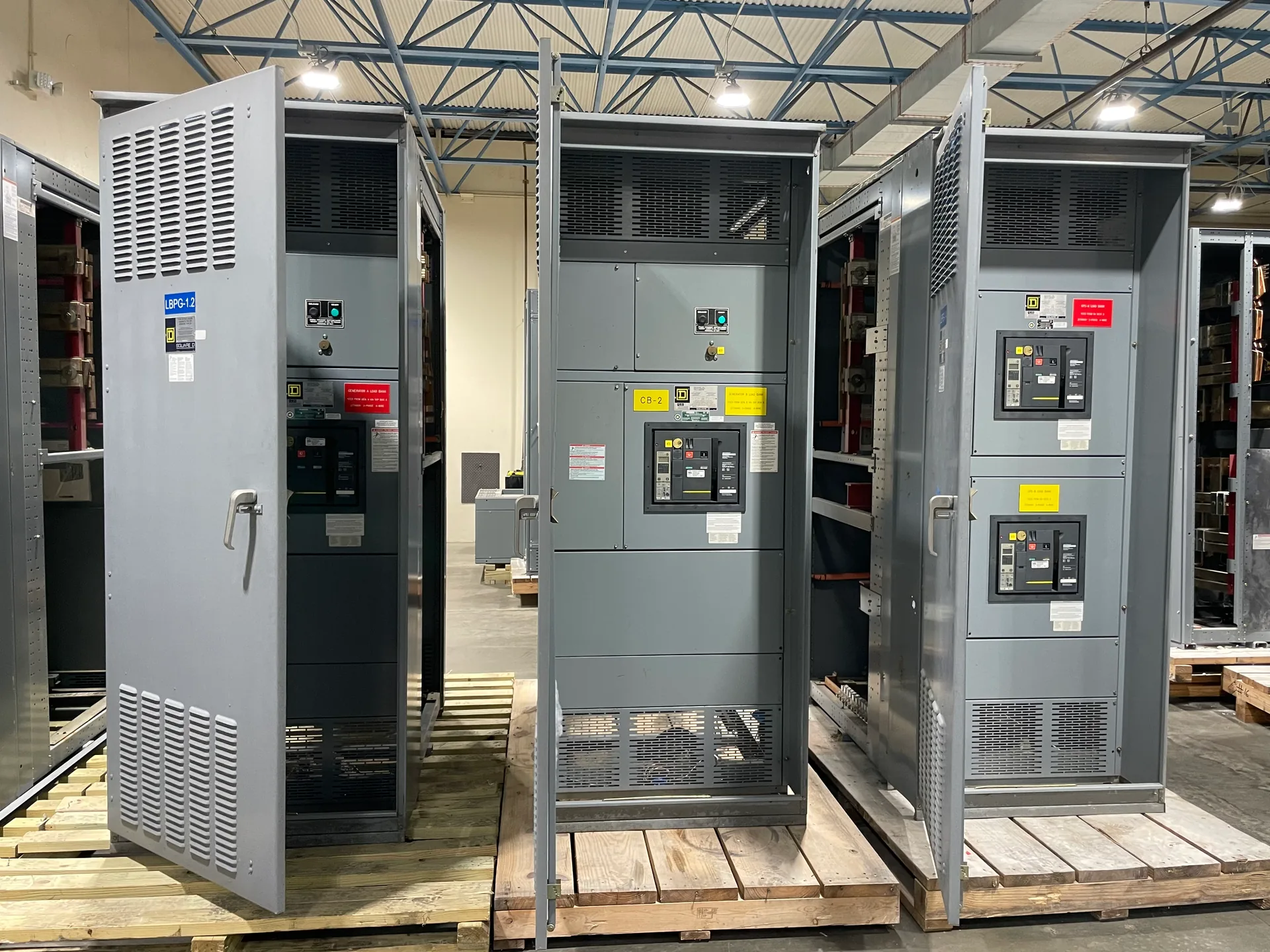
Switchgear maintenance access is a layout decision, not simply a question of leaving space in front of a lineup. Equipment doors, operating handles, removable devices, service tools and the room’s working paths all affect whether planned maintenance can be performed as intended. Switchgear Builder Virginia builds new switchgear to project requirements, with custom configurations and all-American components. Before dimensions are finalized, compare the proposed arrangement with the actual equipment drawings and applicable requirements; clearances, device travel and access needs depend on the selected design and installation.
Map the Work Area
Start by identifying the tasks the room must support: routine inspection, operating controls, opening doors, removing covers, testing, and replacing or withdrawing devices if the design allows it. Each task may need a different approach path and usable space. A front clearance that appears adequate on a floor plan can be reduced by a door swing, nearby wall, column, piping, cable tray, or another piece of equipment. Note those obstructions on the layout rather than relying on a single dimension. Also account for how personnel and tools will reach the work position without blocking an exit or interfering with adjacent equipment. Have the project team verify required working space against the governing rules and actual site conditions. The equipment manufacturer’s drawings can clarify which sides are intended for access, but they do not replace project-specific review of the room and installation.
Check Device Travel
For equipment with withdrawable breakers or other removable devices, check the complete travel path—not just the closed position. The device may need to move from its installed position to a test, disconnected, or fully removed position, depending on the design. Confirm the manufacturer’s drawings for the required front space, handling method, and any lifting or support equipment. Consider where a withdrawn device will be placed temporarily and whether that location blocks an aisle, doorway, or adjacent operating position. The actual dimensions and handling requirements vary by equipment and selected device, so do not assume that one lineup’s clearances apply to another. If the design uses fixed devices, identify the maintenance tasks that replace withdrawal and verify their access needs separately. Resolve these choices during equipment selection and layout review, before room dimensions or surrounding systems are treated as final.
Plan Rear Access
Determine whether the proposed equipment requires rear access for installation, inspection, cable termination, or maintenance. Some arrangements may be designed for front access, while others rely on space behind the lineup; the intended construction must be confirmed from the equipment documentation. Rear access can affect wall placement, cable entry, conduit routing, and the location of other building services. A narrow gap that seems usable on a drawing may not provide enough room for the specific task, tools, or movement required. Conversely, reserving rear space without confirming that the design uses it can consume valuable floor area. Ask the equipment supplier and project design team to identify the required access side and relevant service tasks. Verify dimensions against the selected assembly and site conditions, including any obstructions that could limit access after installation. Treat access needs as part of the layout, not as leftover space.
Coordinate Drawings
Use coordinated drawings to compare the switchgear outline with the room, adjacent equipment, doors, structural features, and planned cable routes. Review both the closed equipment dimensions and the space needed for doors or removable components to move. Identify who will confirm the applicable working-space and egress requirements for the project; these depend on the installation and governing requirements, so a generic rule of thumb is not a substitute for verification. Check that the drawings show the actual equipment configuration under consideration, including access sides and device options. If dimensions or maintenance assumptions change, update the layout before related construction decisions are fixed. Switchgear Builder Virginia offers custom builds, but final configurations, ratings, schedules, and access dimensions are subject to quote and verification. Nationwide shipping is available; shipping coverage does not establish a local office or replace coordination with the project’s responsible design professionals.
Resolve Tradeoffs Early
Maintenance access competes with room area, cable-routing flexibility, and the placement of nearby systems. Reducing the reserved space may make the layout more compact, but it can constrain a specific door, device, or service task. Adding clearance can improve the planned working approach while requiring changes elsewhere in the room. Decide based on the selected equipment and the maintenance activities the owner expects to support, rather than choosing dimensions from another installation. Before approval, document the required access sides, device travel, door swing, temporary handling area, and any unresolved site constraints. Confirm the final arrangement against equipment submittals and applicable project requirements. For applicable low-voltage switchboards, UL 891 assemblies may be specified where appropriate; that designation does not establish the installation’s clearances or resolve layout decisions. Keep those questions separate and have the responsible project team verify each requirement before the design is finalized.