
PRODUCTS / MANUFACTURER DIRECT
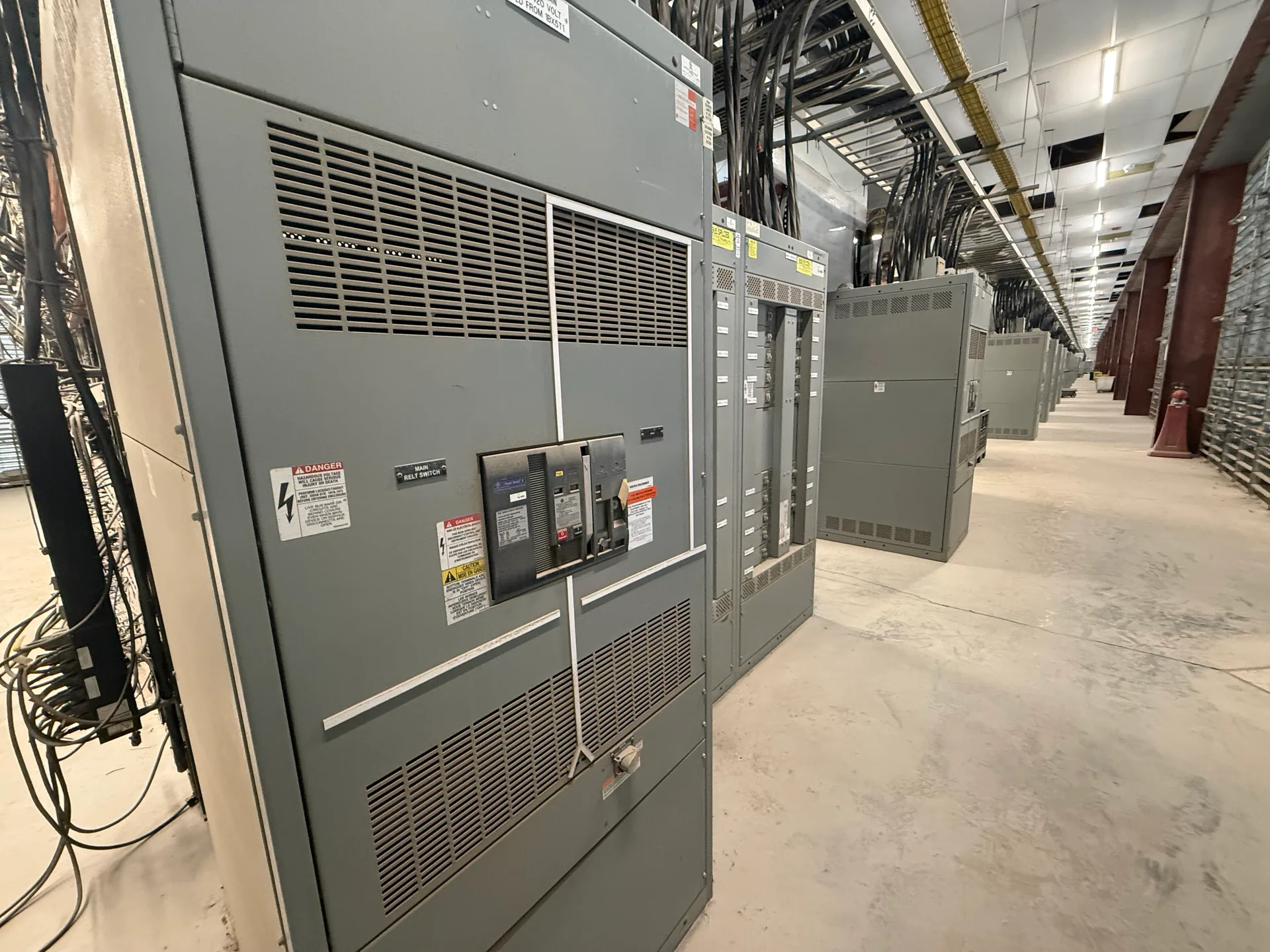
Main lug only (MLO) switchboards receive incoming conductors at lugs rather than through a main overcurrent protective device within the board. That arrangement shifts an important design question upstream: where is the feeder protected, and how does that device coordinate with downstream equipment? Switchgear Builder Virginia manufactures new custom switchboards in the USA using all-American components, with nationwide shipping. For each project, the one-line diagram, available fault current, conductor details, and installation conditions should be reviewed before selecting an MLO configuration. Ratings, termination options, schedules, and applicable standards require confirmation during quoting and engineering review.
How MLO input works
An MLO switchboard provides incoming conductor landing points without an integral main breaker or main fusible switch. The conductors connect to the switchboard bus, while the overcurrent protective device serving that feeder is located upstream. This can suit a distribution arrangement where an upstream breaker or fuse already protects the conductors and equipment, or where the electrical design assigns protection to another part of the system. It does not mean the switchboard or its outgoing circuits need no protection; downstream devices and the upstream protective device must be considered together. The one-line diagram should make the source, feeder protection, and load-side devices clear. Buyers should verify the intended protective device, its location, and how the proposed board interfaces with it before choosing MLO construction.
Upstream protection review
With MLO construction, the upstream protective device is central to the application. Its type, rating, interrupting capability, and settings, where applicable, affect the design review. The available fault current at the switchboard and the protective device’s relationship to the assembly are also items to verify; do not assume a device elsewhere in the system automatically establishes suitability. Provide the source information and upstream device details with the project documents, or identify what remains unknown. The responsible electrical designer should confirm protection and coordination requirements for the complete system. A switchboard quote can then address the specified arrangement rather than infer missing values. If the upstream device may change, note that constraint early: a different device or source condition can affect the review and may call for a revised configuration or rating confirmation.
Conductor termination details
Main lugs must accommodate the actual incoming conductors and installation plan. Confirm conductor material, quantity per phase, size range, insulation, and whether the design calls for top or bottom entry. Also verify lug orientation, bending space, cable approach, and available wireway or gutter dimensions against the drawings and installation conditions. These details affect whether conductors can be routed and terminated as intended; a nominal ampere rating alone does not settle the fit. Do not assume every lug accepts aluminum and copper, multiple conductors, or a particular wire size. Identify the proposed conductor schedule and termination requirements for review. Where the source conductors are not yet selected, flag that uncertainty so the design team can establish acceptable options before release. Final lug and enclosure details remain subject to the project specification and verification.
Check the application fit
MLO may be appropriate when the system design provides upstream feeder protection and the project documents clearly define that interface. Compare it with a switchboard that includes a main device when a local disconnecting or overcurrent-protection point is specified, or when the distribution plan calls for one within the assembly. This is not a universal preference: equipment layout, operating approach, maintenance planning, and the overall protection scheme should guide the choice. Review the one-line diagram, load and feeder information, fault-current data, enclosure location, and applicable project requirements together. Ask the engineer of record to resolve gaps about disconnecting means, protection, or coordination rather than treating MLO as a shortcut around those decisions. The manufacturer can review the stated requirements and identify configuration questions during the quote process; final suitability depends on verified project conditions.
Specify and verify
A useful MLO inquiry includes the one-line diagram, system voltage and phase, bus and feeder requirements, upstream protective-device information, available fault current, conductor schedule, enclosure and entry preferences, and any required standards or project documents. Mark unknown items rather than filling them in by assumption. Switchgear Builder Virginia builds new custom switchboards in the USA with all-American components and ships nationwide. Lead time, ratings, termination details, and the proposed arrangement are confirmed for the specific quotation; schedules are not promised in advance. For applicable low-voltage switchboards, confirm whether UL 891 construction is required and applicable to the project. That standard does not establish medium- or high-voltage switchgear compliance. Before procurement, compare the reviewed submittal with the project documents and have the responsible design professional verify that the selected MLO arrangement matches the intended system.