
PRODUCTS / MANUFACTURER DIRECT
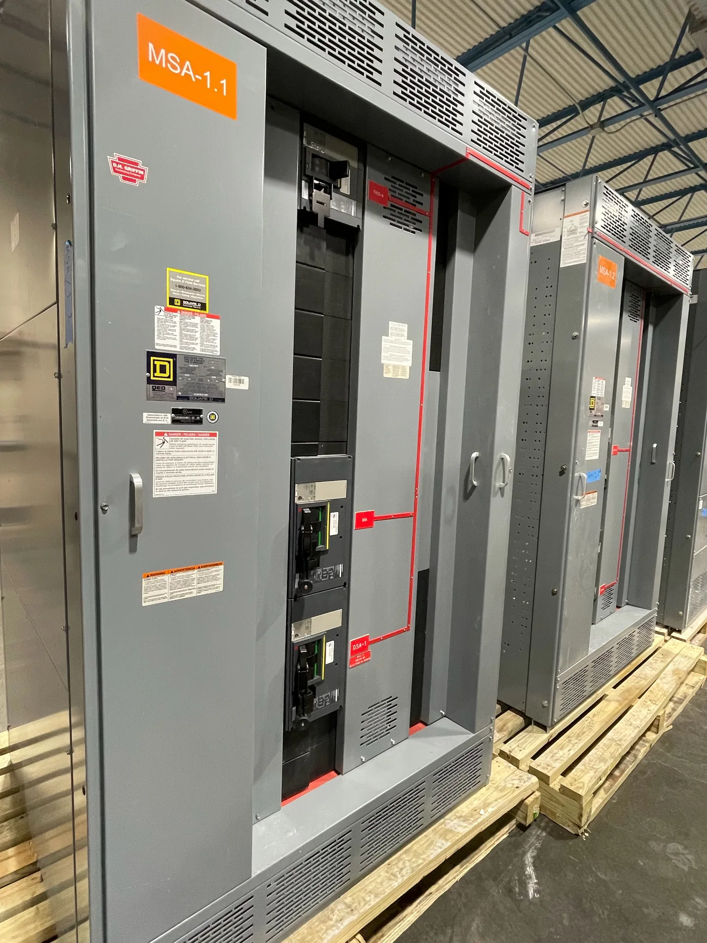
Medium-voltage metering sections help establish how electrical use is measured, where ownership or responsibility changes, and how authorized personnel reach the equipment. The right arrangement depends on the serving utility’s requirements, the system design, and the metering method—not simply the nominal voltage. Switchgear Builder Virginia manufactures custom new switchgear in the USA using all-American components and ships nationwide. Before specifying a section, align the utility, engineer, and purchaser on instrument transformer data, compartment boundaries, isolation provisions, and access. Ratings, schedules, and approvals must be confirmed for the particular project.
Define the Metering Boundary
Start by identifying what the meter must measure and where the utility’s metering responsibility begins. The metering boundary can affect the location of current transformers (CTs), voltage transformers (VTs), test provisions, wiring routes, and access. It should be coordinated with the one-line diagram, service arrangement, utility service requirements, and project ownership documents. Do not assume the preferred location from another facility will be accepted for this installation. Ask the serving utility to confirm its required arrangement and review process before the section is finalized. The engineer and purchaser should also establish which party supplies, installs, connects, and maintains each instrument transformer and associated metering component. Clear answers help prevent a layout that is electrically workable but conflicts with utility access or responsibility expectations. Switchgear Builder Virginia can build a custom new section to project requirements, subject to design review and quotation.
Specify CT and VT Requirements
Instrument transformers must be selected for the actual system and metering application. Provide the engineer and manufacturer with the system voltage, expected load or current range, grounding arrangement, required accuracy class, burden, ratio, frequency, and any utility-specified details. CT selection also involves primary-current capability and secondary wiring requirements; VT selection must suit the system connection and the intended meter inputs. These are coordination inputs, not interchangeable catalog choices. Ask the utility and metering designer to confirm acceptable ratios, accuracy, burden, polarity, connections, and any required nameplate or documentation details. Then verify the selected instrument transformer ratings against the project drawings and equipment configuration before release. A product description alone does not establish a rating, listing, approval, or suitability for a particular system. Switchgear Builder Virginia can review specified requirements for a custom build, with final options and ratings subject to quote and verification.
Coordinate Utility Review Early
Utility approval is a project-specific coordination step, not something to infer from a general equipment description. Identify the serving utility, obtain its current metering and service requirements, and submit the proposed one-line diagram, metering arrangement, and relevant equipment details through the process it specifies. Confirm whether the utility requires particular CT or VT ratios, accuracy, compartment arrangement, test facilities, seals, wiring access, or review milestones. Document the accepted configuration and resolve comments before the design is treated as final. Also assign responsibility for communicating revisions among the utility, electrical engineer, contractor, and equipment supplier. Utility requirements and review timing can vary, so no schedule or approval should be presumed from a previous project. Switchgear Builder Virginia manufactures new custom equipment in the USA; a project’s required features and schedule remain subject to technical review, quotation, and confirmation by the relevant parties.
Plan Isolation and Safe Access
Plan access around the work that authorized personnel must perform, including meter reading, inspection, testing, and instrument-transformer maintenance where applicable. Define compartment doors, barriers, wiring routes, and working clearances from the approved design and governing project requirements. Ask the engineer and utility to identify which components must be accessible to each party and whether the metering compartment needs controlled or sealed access. Isolation provisions should be specified and reviewed as part of the complete system design; do not assume a metering section can be serviced independently of adjacent energized equipment. Switching, isolation, and maintenance procedures belong to qualified personnel following approved site procedures and equipment documentation. This page is not an instruction for live work. Confirm how access doors, interlocks, barriers, and any requested isolation features fit the selected assembly before release, and verify final details against project documents and applicable requirements.
Resolve Layout and Documentation
Compare the proposed section layout with the one-line diagram, equipment lineup, cable entry plan, and room constraints. Confirm the physical position of CTs and VTs, their orientation and connection points, secondary wiring paths, terminal access, and interfaces with adjacent sections. Check that the metering compartment can be reached without creating conflicts with doors, structural elements, cable bends, or the intended maintenance approach. The purchaser should identify required drawings, transformer data, labels, and review submittals early, then confirm which items are included in the quoted scope. Verify dimensions, ratings, options, and interfaces before approving production; changes after design release may affect scope or schedule. Switchgear Builder Virginia offers custom-built new switchgear, short lead times subject to confirmation, and nationwide shipping. The quote and approved project documents—not a general page description—establish the equipment configuration and schedule.