
PRODUCTS / MANUFACTURER DIRECT
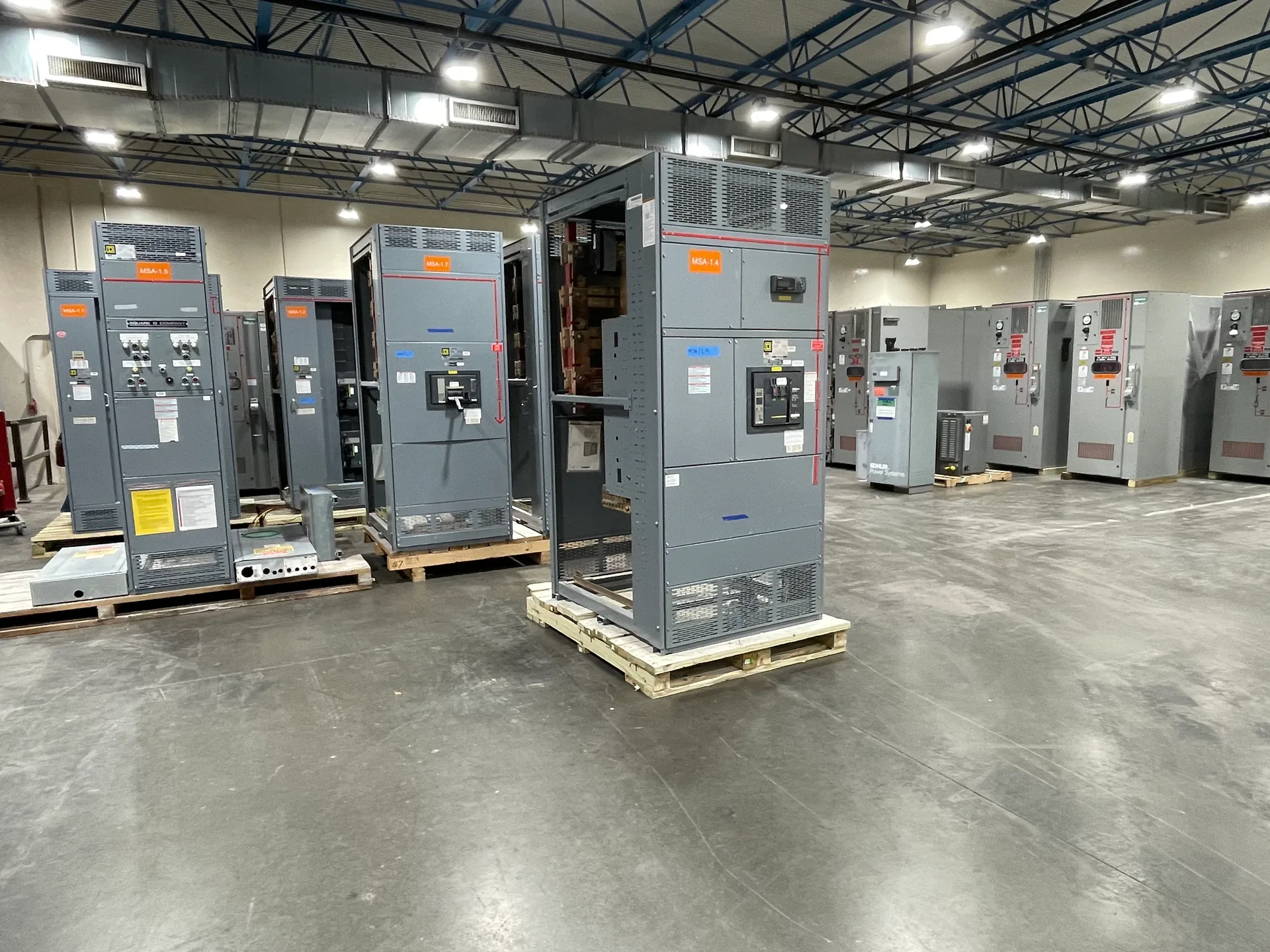
Medium-voltage switchgear lineups organize incoming power, outgoing feeders, metering and bus connections into a coordinated assembly. Their arrangement affects cable routing, maintenance access, protection interfaces and how the lineup fits the electrical room. Switchgear Builder Virginia manufactures new custom switchgear in the USA using all-American components, with nationwide shipping and short lead times subject to project scope and quotation. This page outlines decisions to define with your engineering team; voltage class, ratings, construction details and schedule must be confirmed for the specific project.
Section Functions
An incoming section receives power from the source and may include switching, protection, instrument transformers or other specified components. Feeder sections distribute power to downstream equipment, with each feeder’s protective device and relay interface coordinated to its load and system study. Metering sections accommodate the measurement functions and instrument-transformer arrangements required by the utility, owner or project design. A bus-tie section connects bus segments when the system design calls for that operating arrangement; it is not simply another feeder, and its interlocking and protection requirements deserve separate review. Decide which functions belong in dedicated sections and which may be integrated, based on the one-line diagram, operating sequence and approved equipment design. Confirm each section’s function, device arrangement and interfaces before drawings are released, since changing the lineup arrangement later can affect connections and coordination.
Cable Access
Cable entry and exit locations influence section layout, termination space and the route from the lineup to conduits, trenches or overhead cable supports. Establish whether power cables enter from above, below or another project-defined direction, and identify which sections need access for incoming, feeder, tie or instrument-transformer conductors. Review cable size and quantity, bending and termination requirements, phase arrangement, grounding provisions and any separation or shield-termination details with the responsible designer and equipment supplier. These are design inputs, not assumptions that every enclosure accommodates every routing method. Confirm working clearances and access-panel locations against room plans and applicable project requirements; avoid letting doors, barriers or adjacent equipment obstruct planned cable work. Early cable-access decisions can reduce field conflicts, but the final arrangement depends on verified drawings, specified equipment construction and the installation conditions at the site.
Section Splits
A lineup may be divided into shipping sections to suit transport limits, building access and the installation sequence. The split locations should be coordinated with bus connections, enclosure construction, lifting and handling plans, and the space available for reassembly. Ask the project team to identify the route from receiving area to final room, including doors, turns, floor transitions and restrictions that could affect the largest section. Also establish whether the design requires field bus connections, cable interconnections or other work at section joints, and who is responsible for completing and inspecting those steps. A shipping split is a logistical decision as well as an electrical and mechanical detail; it should not be chosen only to simplify transport. Confirm the proposed split plan, interfaces and site responsibilities on project documents before fabrication, because dimensions, ratings and permitted assembly methods are design-specific and must be verified.
Relay Interfaces
Relay and control interfaces connect the lineup’s protective devices to the project’s sensing, control, communications and trip requirements. Define which functions are provided in each incoming, feeder or bus-tie section, and identify required current- and voltage-sensing inputs, auxiliary contacts, control power, trip circuits, alarms and external signals. Specify relay models or functional requirements only after the protection design establishes what is needed; compatibility, wiring details and available options must be confirmed for the selected equipment. Coordinate terminal points, cable entry and interface responsibilities with the protection engineer, controls integrator and other project parties. If communications are required, document the protocol and data points rather than assuming a particular network feature is included. Review schematics and settings responsibilities before release, while keeping final protection coordination tied to the system study. This planning clarifies boundaries between equipment and site systems without presuming unverified capabilities.
Class And Ratings
“Medium voltage” alone does not specify a lineup’s electrical duty or construction. Project documents should identify the system voltage and required equipment class, continuous current, interrupting or withstand duties, frequency, grounding arrangement and environmental conditions, as applicable to the design. Confirm these values against the source, available fault information, connected loads and protection study; do not infer a rating from a product label or a numerical topic. The required standards, testing, approvals and any listing expectations should be stated for review and verified for the exact proposed assembly. Also coordinate enclosure requirements and room conditions with the project specification. Switchgear Builder Virginia can develop a custom new lineup around documented requirements, but ratings, available configurations, schedule and scope remain subject to engineering review and quotation. Compare drawings and submittals against the project criteria before approval, and resolve exceptions explicitly rather than relying on assumed equivalence.