
RATINGS / MANUFACTURER DIRECT
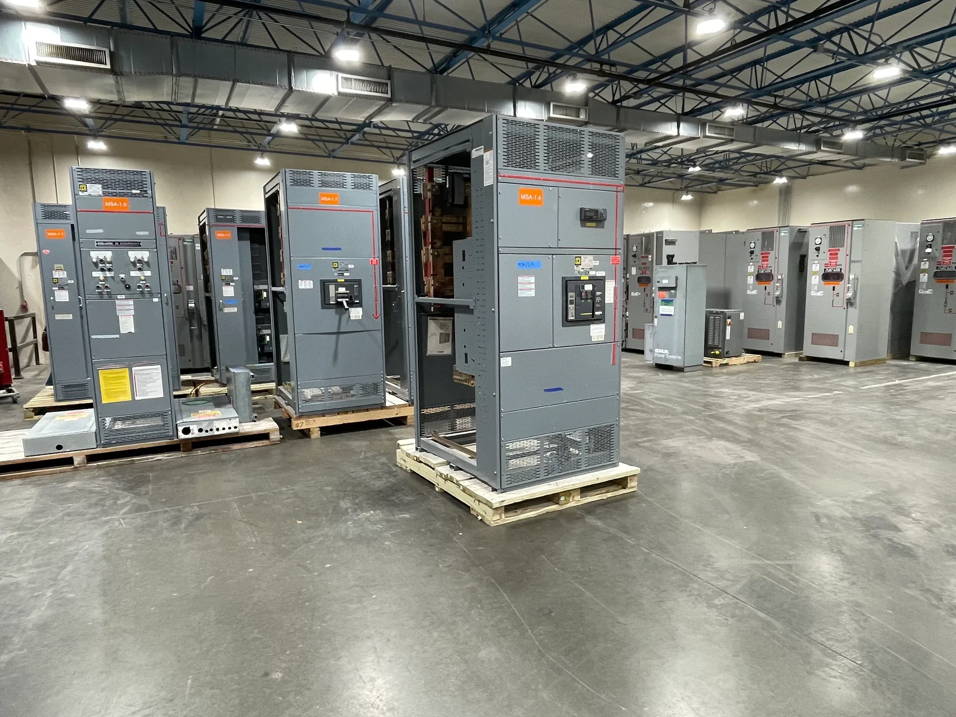
An 800 A label is a starting point, not a complete lineup specification. The right design depends on calculated demand, the equipment’s voltage and application, feeder requirements, available fault-current information, and the space and access provided. Bus arrangement, enclosure dimensions, and connection details matter alongside the main device: a mismatch can complicate installation or leave little room for planned circuits. Switchgear Builder Virginia manufactures new custom equipment in the USA using all-American components, with nationwide shipping. Ratings, construction details, applicable standards, and schedule are subject to project review and quotation.
Start With Calculated Demand
An 800 A main does not mean a building will continuously use 800 amperes, nor does the label prove that the lineup fits the load. Start with the project’s demand calculation and the electrical characteristics of the service, including voltage, phase, frequency, and grounding arrangement. The engineer or responsible electrical professional should establish the applicable load basis and account for the actual distribution plan. Identify loads that may operate together, equipment with distinct starting or operating behavior, and any planned expansion that has a credible scope. Avoid sizing from a single nameplate total or assuming every future circuit will be used simultaneously. The result should explain why an 800 A configuration is appropriate and provide a basis for reviewing the main device, bus, and feeder schedule. Final ratings and construction details require project-specific verification before release for manufacture.
Coordinate Main, Bus, and Feeders
Treat the main-breaker rating and the bus rating as separate items to specify and verify. An 800 A main alone does not establish the rating of every bus section, vertical section, connection, or outgoing feeder. Prepare a one-line diagram and feeder schedule showing the intended circuit count, device types, ratings, and locations. Then check that the proposed bus arrangement and distribution sections accommodate those requirements, including any planned spare positions. A spare space is useful only if its position and the lineup’s construction can support the future device and connection. Ask the design team to resolve any required coordination, interrupting ratings, and available fault-current information rather than infer them from the 800 A figure. For applicable low-voltage switchboards, UL 891 requirements may be relevant; applicability and the specific assembly must be confirmed for the project.
Plan Physical Arrangement
The enclosure and lineup arrangement affect more than appearance. Confirm the available room dimensions, entry routes, installation orientation, and the location of cable or bus connections before settling on section layout. Incoming conductors may approach from above or below, while outgoing feeders may need a different path; the actual design and termination provisions require review against the project drawings and conductor requirements. Consider working access, door and panel clearances, adjacent equipment, and the route for future feeder work. Do not assume an 800 A lineup has a standard width, depth, or section count: those dimensions depend on the chosen devices and arrangement. Provide site constraints and relevant plans for quotation, and have the responsible project team verify installation clearances and applicable requirements. A well-coordinated layout can reduce field conflicts without sacrificing useful feeder capacity.
Review Fault and Coordination Data
The 800 A value describes a current rating, not the assembly’s ability to withstand or interrupt a fault. The design team should provide the available fault-current information at the equipment location and establish the required ratings and protective-device coordination for the system. Verify the proposed main and feeder devices against that information, including any specified interrupting rating and short-circuit or withstand requirements applicable to the assembly. Do not select those values from the service amperage alone. Protection settings, selectivity objectives, and upstream or downstream device relationships can affect equipment choices, but must be evaluated using project-specific system data and qualified engineering review. If the fault study or utility information is incomplete, identify that open item before finalizing the specification. Switchgear Builder Virginia can review defined project requirements for a custom new build; final ratings remain subject to verification and quotation.
Specify Future Capacity Clearly
Future capacity should be described as concrete requirements, not a general request for room to grow. List likely additional feeders, anticipated device types and ratings, preferred section locations, and any known load changes. This lets the design team evaluate whether spare spaces, bus provisions, enclosure dimensions, and cable access can support the intended expansion. More unused capacity can add cost and occupy valuable room, while too little may lead to a larger redesign later; the appropriate balance depends on the project’s forecast and constraints. Confirm which provisions are included in the quoted scope and which would require later engineering or equipment changes. Switchgear Builder Virginia manufactures new custom switchgear in the USA using all-American components and ships nationwide. Lead times and the final configuration are established through project review and quotation; no schedule should be assumed until confirmed for the specific order.