
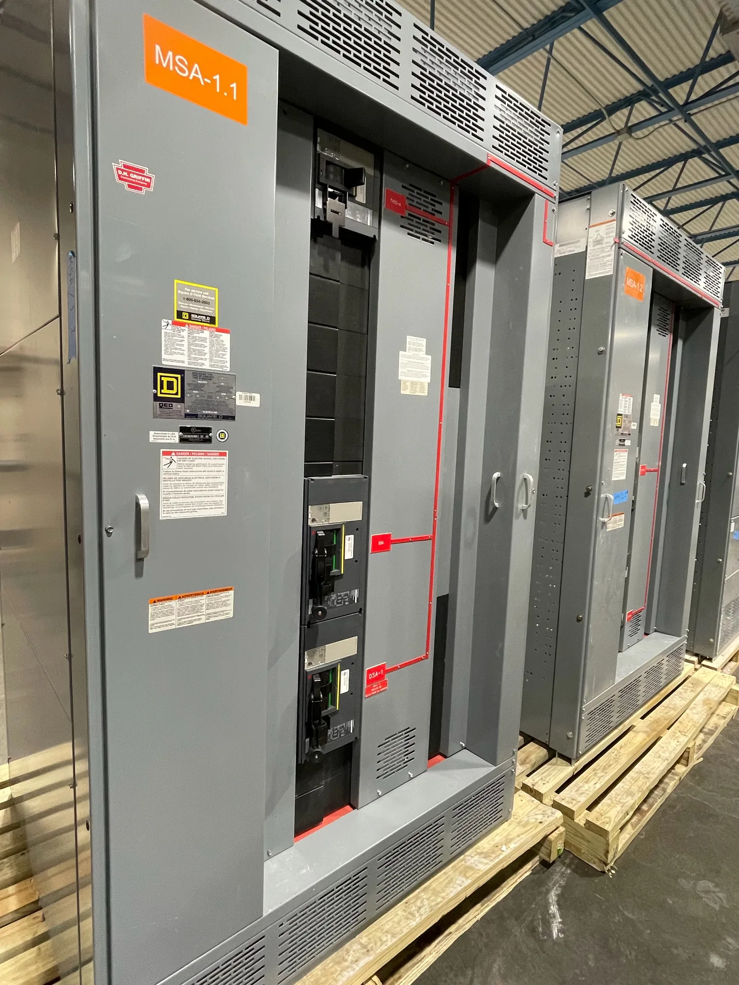
SERVICES / MANUFACTURER DIRECT
Busbar fabrication begins with the electrical and mechanical demands of the switchgear assembly—not with a material choice in isolation. Conductor material, current requirements, insulation, bends, joints, and connection drawings all affect fit, heat management, and assembly layout. For a new custom switchgear build, define these inputs early and confirm the applicable design and testing requirements with the project team. Switchgear Builder Virginia manufactures new switchgear in the USA using all-American components, with nationwide shipping; schedules and ratings are subject to quote and verification.

Choose the Conductor
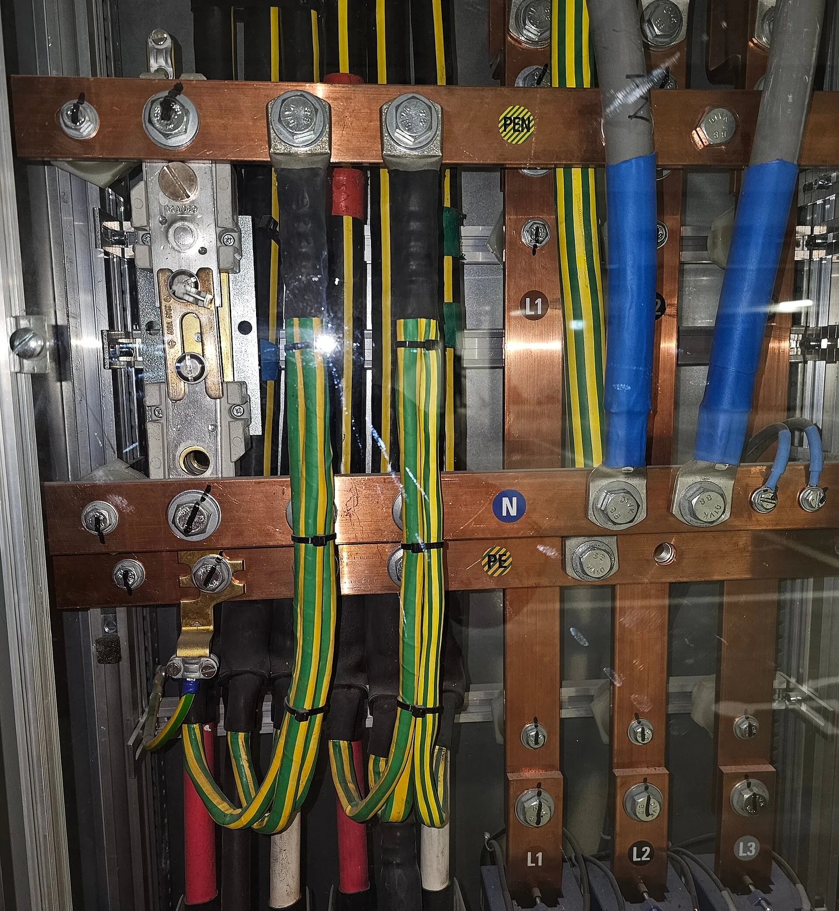
Copper and aluminum are common busbar conductor options, but they are not interchangeable by simply matching dimensions. Their conductivity, weight, material cost, joining methods, and space needs differ, so the right choice depends on the assembly design and project requirements. Specify the preferred material if the project standard requires one; otherwise, ask the design team to evaluate the tradeoffs for the intended application. Also clarify whether the bus must connect to equipment or conductors made from a particular material, and identify any material compatibility requirements at interfaces. Surface finish, plating, and protective treatment should be specified only when required by the design or procurement documents. Confirm the conductor material, dimensions, and connection details on approved drawings before fabrication. This helps prevent late changes that can affect clearances, supports, joint preparation, or the fit of the completed switchgear assembly.
Define Current Requirements
A busbar’s current rating cannot be determined from conductor material or cross-sectional area alone. The complete assembly design and its operating conditions matter, including enclosure arrangement, spacing, ventilation, connection points, and the project’s specified temperature limits. Provide the required continuous current and any relevant system information so the design can be reviewed as a whole. Where applicable, clarify whether the project also requires evaluation of short-circuit withstand, rather than treating that as the same requirement as continuous current capacity. Do not assume an existing rating transfers to a changed bus layout or a different assembly. Ratings must be established and verified for the specific configuration and applicable requirements. Share the governing specifications and one-line diagram, then review the proposed rating and any limitations before approval. Final schedules and ratings are subject to quote and verification; numerical values in a project brief alone do not establish a product rating.
Specify Insulation
Busbar insulation may be needed to address electrical clearances, protection from accidental contact, environmental exposure, or a project-specific design requirement. The correct approach depends on the bus arrangement, operating conditions, and the assembly’s evaluated design. First determine whether the project calls for insulated bus, bare bus, barriers, or another method of separation; do not assume that coating every conductor is automatically preferable. Insulation can affect heat dissipation, joint access, inspection, and the dimensions of the assembly. If insulation is specified, identify the required material or performance criteria, coverage boundaries, and treatment at bends and joints. Also note whether the project requires particular documentation or verification for the selected construction. Confirm these details against the drawings and applicable requirements before fabrication. Any insulation construction, approval, or testing must be confirmed for the specific design rather than inferred from a material description alone.
Plan Bends and Joints
Bus bends and joints determine how conductors route through the assembly and connect to devices, incoming or outgoing conductors, and adjoining sections. Their geometry must account for available space, phase arrangement, required clearances, support locations, and access for assembly and inspection. Provide the intended bus path and connection points, including orientation and any dimensional constraints from the enclosure or equipment layout. Joint design should identify mating surfaces, fastener arrangement, and any required surface preparation or plating. Avoid specifying a bend radius or joint detail by assumption: the appropriate dimensions depend on conductor material, thickness, fabrication method, and the approved assembly design. Changes to bends or joints can affect fit and electrical performance, so revisions should be reviewed across the complete layout. Confirm final dimensions and connection details on coordinated drawings before release. Fabrication and assembly details remain subject to the project’s design requirements and verification.
Coordinate the Drawings
Connection drawings translate project requirements into buildable bus geometry. Useful documents include the one-line diagram, equipment arrangement, elevations or section views, terminal and device details, conductor schedules, and relevant specifications. Identify source and load connections, phase sequence, neutral and ground requirements where applicable, interface dimensions, and any field connection constraints. Mark which dimensions are fixed and which may be coordinated during design review. Resolve drawing conflicts before approving fabrication; an overall layout can look correct while a terminal location or mating face remains undefined. The review should also confirm conductor material, current requirements, insulation approach, bends, joints, and any required design or testing criteria. For custom new switchgear, Switchgear Builder Virginia can review project requirements for a quoted build. Applicable UL 891 assemblies may be considered where appropriate; applicability and the specific assembly requirements must be verified. Final drawings and ratings require project-specific review and confirmation.