
SERVICES / MANUFACTURER DIRECT
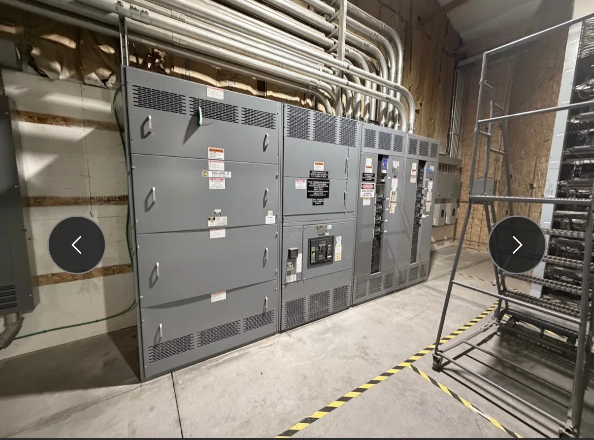
A switchgear controls upgrade starts with understanding what the existing equipment must do—not simply replacing relays or changing drawings. Switchgear Builder Virginia manufactures new, custom switchgear and can develop a project scope around documented control requirements and interfaces. For a controls-focused project, buyers should define the operating sequence, control power, interlocks, field wiring, and acceptance criteria before equipment is specified. Existing-system details and proposed ratings require review and verification; schedules are subject to quote.
Define the operating sequence
Write down how the equipment is expected to operate in normal, alternate, and abnormal conditions. Identify which devices initiate an action, which conditions block it, what indications operators need, and how the system returns to its normal state. A sequence narrative paired with a one-line diagram and control schematics gives the design team a clearer basis than a general request to modernize controls. Include manual and automatic modes, transfer logic, alarms, and any required time delays, but do not assume existing settings should carry forward unchanged. Confirm the intended sequence with the owner and relevant system stakeholders before design begins. This makes it easier to distinguish essential functions from legacy behavior that should be evaluated, and helps establish a reviewable scope for new custom equipment without assuming the existing switchgear can be modified in place.
Record interlocks and control power
Document each electrical and mechanical interlock that affects operation, including the devices involved, the condition that permits or prevents an action, and the intended response to a fault or loss of control power. Identify control-voltage sources, nominal values, polarity or grounding conventions where applicable, and any separate supplies for protection, indication, or communications. These details influence component selection, wiring architecture, and the way a new assembly can coordinate with customer equipment. Do not treat a voltage reading or an old drawing as definitive design authority; records may be incomplete, and field conditions need qualified review. Specify which interlock functions must be retained, changed, or newly provided, then resolve conflicts before fabrication. The final design basis should state assumptions clearly and flag any conditions requiring customer confirmation or engineering approval.
Map wiring and interfaces
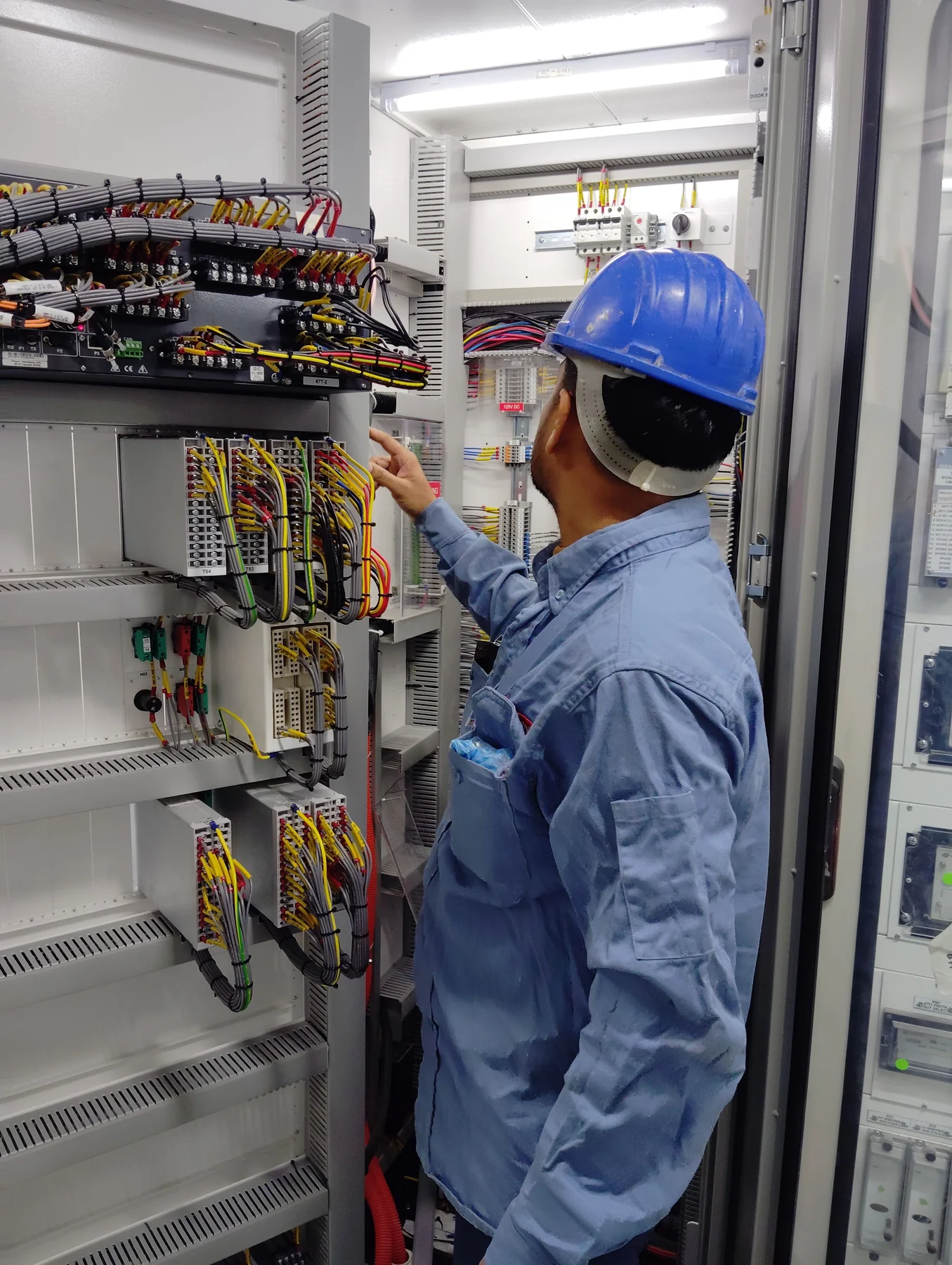
A useful wiring package traces signals from their source to their destination. List terminal references, cable identifiers, connector details, wire functions, and the equipment or customer system at each interface. Note which signals are hardwired and which, if any, rely on a communications link; identify ownership boundaries and who supplies external devices or cables. For interfaces to a building management, generator, transfer, monitoring, or supervisory system, define the required status points, commands, alarms, and expected behavior during loss of communication. Do not assume protocols, point counts, or compatibility from equipment labels alone. A coordinated interface schedule helps the manufacturer design terminals and controls to suit the agreed scope, while giving the customer and other contractors a basis to review connections before installation. Verify all interface details against approved project documents.
Specify acceptance testing
State what acceptance means before equipment is ordered. The project specification can identify the drawings and submittals to review, required visual and wiring checks, functional scenarios, records to provide, and the people responsible for witnessing or approving each step. List each sequence and interlock that must be demonstrated, including expected indications and responses to defined simulated conditions. Clarify whether tests concern the new assembly only or also depend on customer equipment, site wiring, protective devices, or external controls. Those boundaries matter because a factory check cannot establish the behavior of every connected system. Test methods, applicable standards, approvals, and documentation should be confirmed for the specific project rather than assumed. Acceptance requirements agreed early can reduce disputes about scope, readiness, and what evidence is needed at handoff.
Plan the new-equipment scope
A controls upgrade may involve a new switchboard or switchgear assembly, a replacement control section, or a broader equipment scope; the right approach depends on condition, compatibility, ratings, space, and project constraints. Switchgear Builder Virginia manufactures new custom equipment with all-American components and ships nationwide. Applicable low-voltage switchboards may be specified as UL 891 assemblies, subject to project applicability and verification; that designation does not apply to medium- or high-voltage switchgear. Provide equipment data, available drawings, site constraints, required functions, and the desired interface and acceptance documents so the scope can be evaluated. Any proposed ratings, features, approvals, testing, and schedule remain subject to review and quote. Do not assume a new assembly will fit or connect to existing equipment until dimensions, electrical characteristics, and connection details are verified.