
SERVICES / MANUFACTURER DIRECT
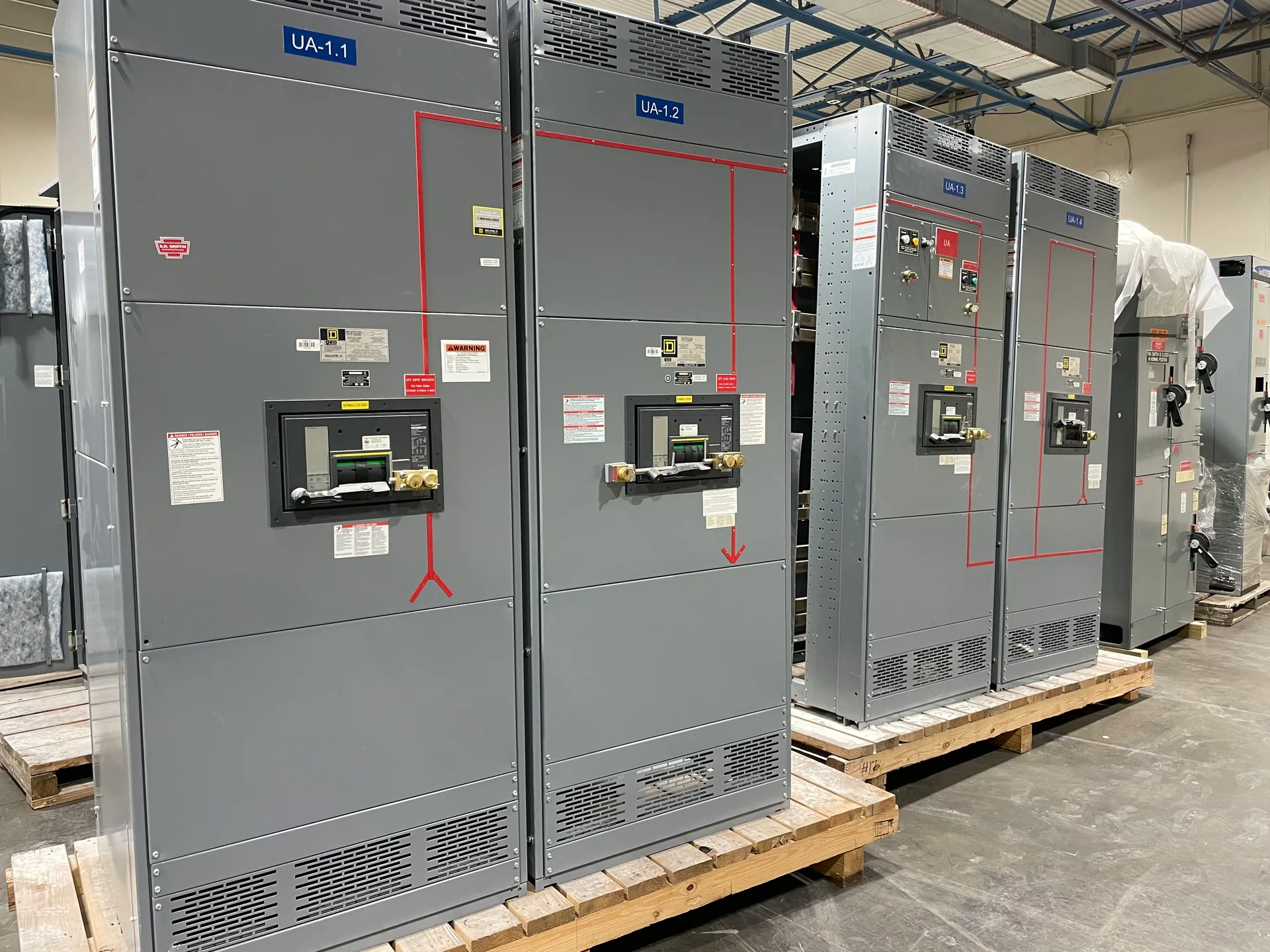
Switchgear functional verification checks whether specified control points and operating sequences behave as intended before equipment is energized. For a new switchboard or switchgear package, the useful starting point is an approved sequence, coordinated drawings, and a clear boundary between factory checks and work at the installation site. Switchgear Builder Virginia manufactures custom new equipment in the USA using all-American components, with nationwide shipping and short lead times subject to project scope and quote. Verification scope, available test provisions, ratings, and schedule must be confirmed for each order. The points below help buyers define what they need without confusing functional checks with energization or field commissioning.
Define the sequence
Begin with the approved control narrative: what initiates an operation, what conditions must be satisfied, what indication follows, and what should happen if a permissive is absent. Translate each requirement into a checkable step tied to a drawing reference, device tag, or terminal point. This makes discrepancies visible before test time is spent and gives the project team a common basis for acceptance. Avoid relying on informal descriptions such as “normal operation”; document the expected state of breakers, indicators, alarms, interlocks, and control power for each scenario. Where the narrative conflicts with approved drawings or specifications, resolve the conflict through the project’s designated engineering and approval process before treating the sequence as a test criterion. The manufacturer can review the requested scope against the quoted design, but the project team must identify which documents govern and who approves changes.
Map points clearly
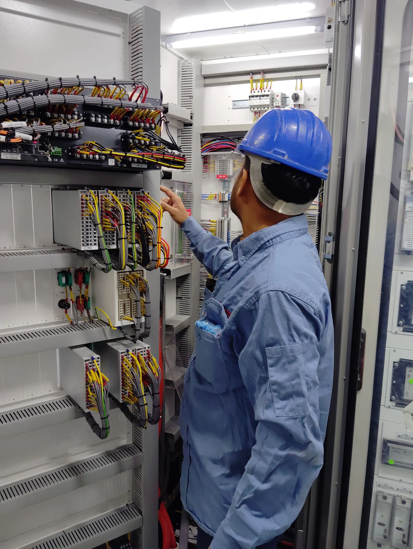
Point-to-point verification concerns correspondence between specified control points and their intended terminals, devices, or indications. A useful checklist identifies each point by consistent tag, source and destination, expected normal condition, and the drawing or schedule that defines it. Separate discrete status contacts from commands, alarms, analog signals, and communications points; they may require different methods and acceptance criteria. Confirm the required interface boundary, especially where switchgear connects to relays, remote controls, building systems, or customer-supplied equipment. Those external devices and wiring may fall outside the manufacturer’s package unless the quote explicitly includes them. Agree whether records should capture point identification, observed state, exceptions, and resolution. Naming conventions and terminal assignments can change during design, so establish a document revision and change-control method rather than assuming an early point list remains current through production and installation.
Test operations safely
Operation checks should follow the approved sequence and defined test conditions, not improvised actions. Depending on design and agreed scope, checks may cover control-circuit responses, interlock logic, local indications, alarms, and selected open-close commands. Confirm which devices and auxiliary supplies are included, what test interfaces are available, and whether customer or third-party controls are required. Some functions depend on equipment or signals beyond the switchgear assembly; those dependencies must be identified before deciding a test can demonstrate the complete end-to-end result. Test plans should state expected outcomes, permitted operating modes, responsibilities, and stop conditions. Do not infer that a successful control check proves suitability for energization, protection coordination, or every system condition. Any test method involving hazardous energy or access to electrical equipment belongs to qualified personnel following approved site procedures, not to an informal buyer checklist.
Separate verification stages
Functional verification is not the same as energization. It evaluates specified control behavior under agreed test conditions; energization introduces electrical power and requires separate readiness decisions, approvals, and site controls. Field commissioning is broader and may include installation review, system-level coordination, settings confirmation, interface checks, and documented performance activities defined by the project. The responsible engineer, owner, contractor, and commissioning provider should assign these boundaries in writing. A factory check cannot establish that field wiring is correct, that external devices communicate as intended, or that the installed system meets every project requirement. Likewise, a field commissioning plan should not presume factory tests are included unless the purchase documents say so. This distinction helps buyers request the right records, budget responsibilities, and schedule dependencies without treating one milestone as evidence that all later acceptance steps are complete.
Specify scope and records
For a quote, provide the approved sequence, current schematics, point lists, interface boundaries, requested test location, witness needs, acceptance criteria, and desired records. Identify whether checks are required during manufacturing, at the installation site, or both; these are different scopes with different dependencies. Ask which functions are included, which require customer-furnished controls or signals, how exceptions are recorded, and how design revisions affect the plan. Confirm any requested approvals, listings, ratings, or test documentation against the actual equipment specification; their availability must not be assumed from a general description. Switchgear Builder Virginia can build to a custom project specification, while test scope, schedule, and requirements remain subject to review and quote. UL 891 applies only where the equipment is an applicable low-voltage switchboard and that requirement is confirmed for the project. Clear documentation makes verification results useful for handoff and later troubleshooting.