
SERVICES / MANUFACTURER DIRECT
Switchgear shop drawings turn project requirements into a coordinated design that buyers, engineers, and installers can review before fabrication. For a custom build from Switchgear Builder Virginia, the drawing package can show the proposed arrangement, electrical relationships, dimensions, and connection details, subject to project scope and verification. Agree early on required formats, review participants, and approval milestones. Clear comments on one coordinated set help separate design changes from corrections and keep decisions traceable. The drawings support coordination; they do not replace the project’s specifications, approved documents, or field verification.
One-line and system intent
The one-line diagram summarizes the proposed electrical arrangement: incoming sources, main devices, bus connections, distribution sections, and other specified equipment. Buyers should compare it with the project one-line and specifications, checking device functions, section sequence, source relationships, and any required metering or control provisions. A drawing may identify proposed equipment without establishing its final rating or suitability; confirm voltage, current, interrupting capacity, and other applicable requirements against the project documents and formal quote. If source configuration, future spaces, or alternate operating arrangements are important, identify them before design review rather than relying on a general note. Changes to the one-line can affect physical layout, connections, and coordination with other trades, so route those comments to the responsible project engineer. A shop drawing communicates a proposed build for review; it does not independently authorize a change to the design basis.
Sections, elevations, and access
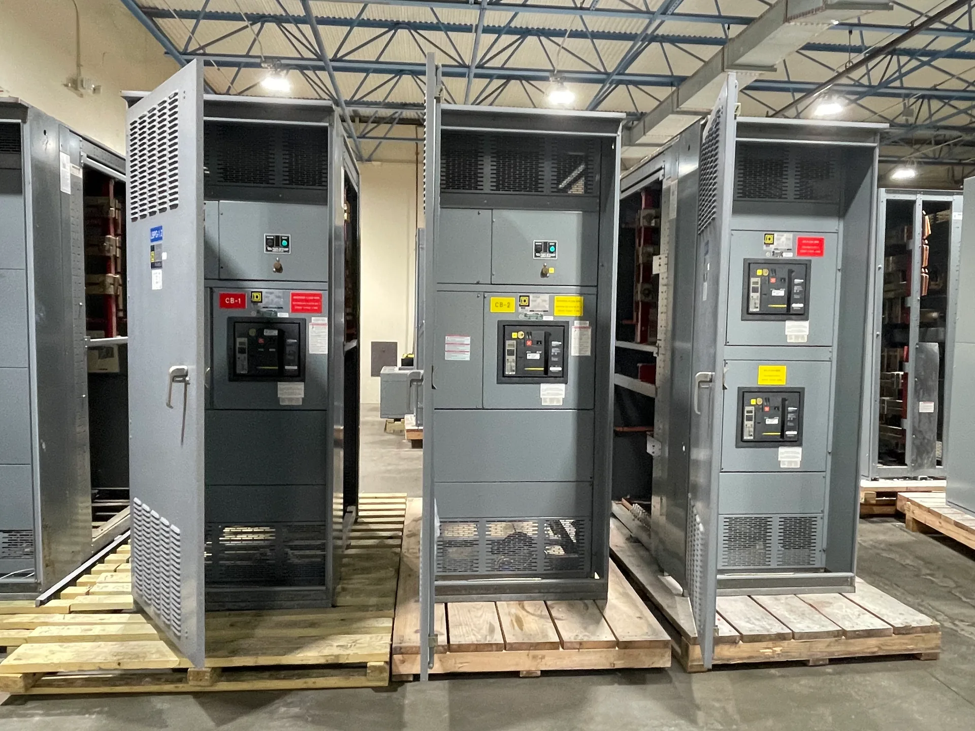
Section elevations show how the proposed lineup is divided into cabinets or functional sections and where major devices, barriers, doors, and access points may sit. Check the overall arrangement against room plans, equipment clearances, cable entry direction, adjacent gear, and the intended installation path. Confirm that dimensions are coordinated with the latest architectural and electrical documents, including any housekeeping pad, trench, or overhead constraint supplied for the project. The drawing should distinguish overall dimensions from section widths and identify relevant front, rear, or side access where applicable. Do not assume a typical arrangement fits a particular room: options such as front-only access, rear access, or different termination zones must be reviewed for the specified equipment and project. Flag conflicts with walls, doors, cable routes, or service space in a consolidated comment set. Field measurements and final installation conditions remain matters for project coordination.
Dimensions and terminal details
Dimensioned drawings help coordinate mounting, conduit, cable, bus, and control connections, but their level of detail depends on the package and project requirements. Buyers should identify which dimensions must be fixed for room coordination and which interfaces need confirmation by the installer or engineer. Terminal details may indicate connection locations, orientation, quantities, or proposed provisions; they should be checked against conductor plans, lug or termination requirements, cable bending space, and the approved equipment scope. Avoid inferring conductor sizes, lug suitability, or field connection methods from a general elevation. Provide the manufacturer with verified project information, including entry direction and interface constraints, and ask that unresolved items be marked clearly. For custom builds, a requested dimension or terminal arrangement is not established until it is reviewed and documented in the applicable drawing set and quote. Confirm revisions before construction and installation planning.
Review and approval cycles
A useful review cycle begins with an agreed document list, responsible reviewers, submission format, and target dates established for the project; actual schedules depend on scope and confirmation. Reviewers should return coordinated comments that cite sheet, detail, and requested action, separating corrections from proposed scope changes. The design team and manufacturer can then resolve questions, revise affected sheets, and identify items still needing project direction. Approval should be recorded by the authorized parties using the project’s stated process. Approval drawings are intended to document the proposed configuration for review before fabrication; they are not the same as record drawings. A returned mark-up alone may not resolve a technical conflict or authorize a change. Buyers should verify the approved revision, open items, and any required engineering disposition before relying on the package for procurement coordination or construction.
Approval versus record drawings
Approval drawings represent the design submitted for review, including proposed layouts and interfaces. Record drawings, by contrast, document the configuration as completed or revised for the project record, to the extent that this deliverable is specified, supported by supplied information, and confirmed in the order. Do not treat an approval stamp as proof that field conditions match the drawings, or assume that record drawings are automatically included. Before ordering, define whether the project requires marked-up changes, revised final sheets, electronic files, or another closeout format, and identify who will provide verified field changes. Switchgear Builder Virginia manufactures new custom switchgear, with direct USA manufacturing, all-American components, short lead times, and nationwide shipping; schedules and equipment details are subject to quote and verification. For applicable low-voltage switchboards, ask whether UL 891 assemblies are required and confirm the applicable scope in project documents.