
APPLICATIONS / MANUFACTURER DIRECT
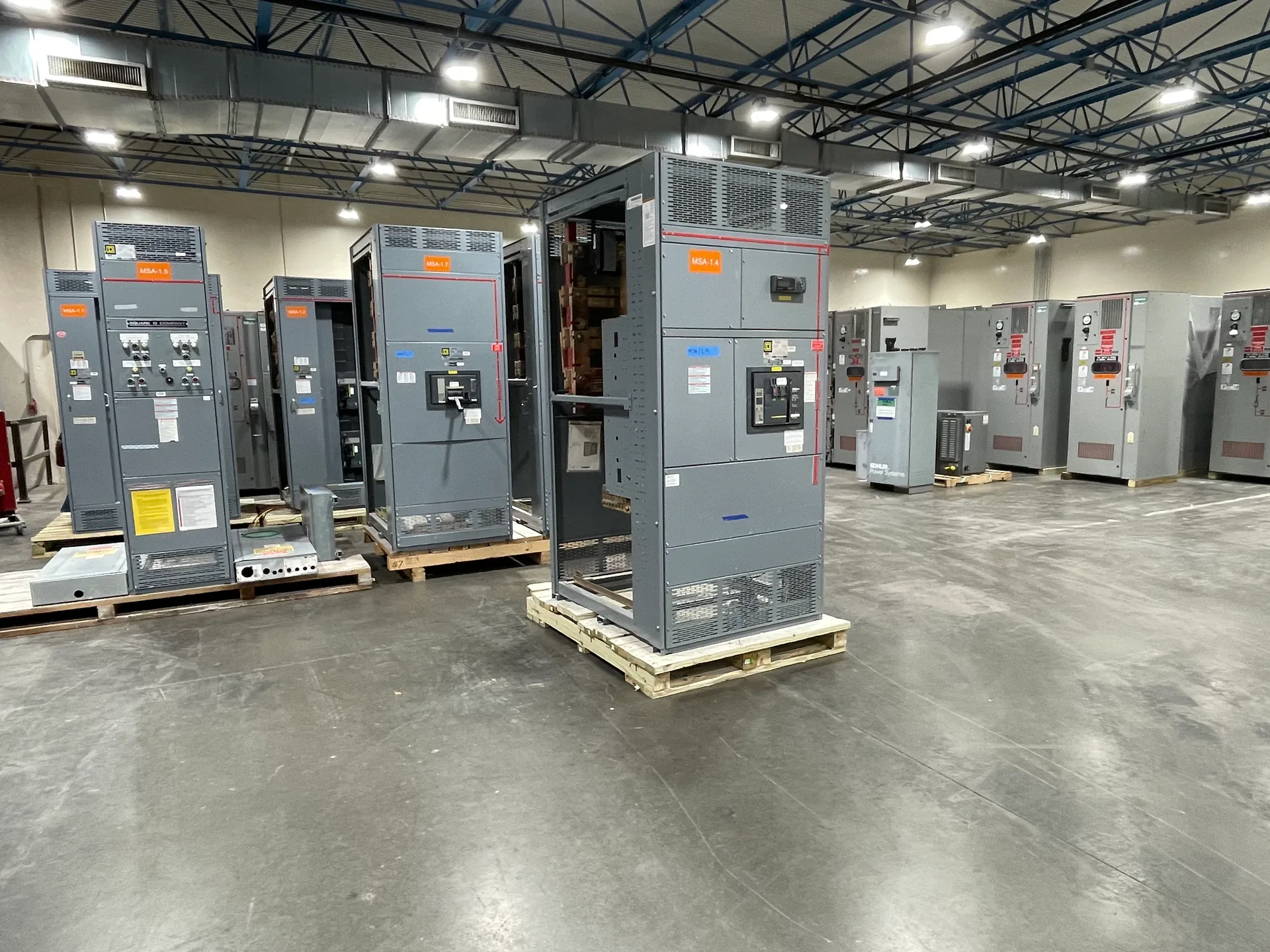
Data hall distribution starts with the facility’s actual power architecture, not a presumed redundancy model. Source paths, transfer points, downstream boards and future capacity must work together under the operating conditions the project requires. Switchgear Builder Virginia manufactures new, custom switchgear in the USA using all-American components, with nationwide shipping and short lead times subject to project scope and quote. For applicable low-voltage switchboards, UL 891 assemblies may be specified and verified. The design team should confirm ratings, coordination, physical interfaces and maintenance boundaries before equipment is quoted.
Map the Source Paths
A data hall may receive power through utility service, generator-backed sources, or a combination defined by its resiliency plan. The one-line diagram should show where sources enter, where transfer or paralleling equipment sits, and which downstream sections each path can serve. Do not infer that two incoming feeders create independent paths: shared bus, controls, protection, or upstream equipment may remain common points. Identify normal and alternate operating states, including which loads remain served during a planned outage. A custom switchboard can be arranged around the specified source and feeder layout, but the actual voltage, current, fault-duty, enclosure, and separation requirements need project verification. Clear source-path documentation gives the manufacturer and electrical engineer a common basis for reviewing interfaces, space, and ratings before fabrication details are finalized.
Coordinate Downstream Loads
Downstream distribution should reflect the load schedule and the physical division of the hall, rather than a generic count of racks or rooms. List major loads, expected demand, feeder destinations, spare ways, and any dedicated branches that need separate operation. Then review how the selected board interfaces with transformers, panelboards, busway, UPS equipment, or other specified components; those products and their ratings are not assumed by a switchgear quote. Feeder sizes, protective-device selections, interrupting ratings, and coordination depend on the system study and project requirements. A practical tradeoff is whether to concentrate distribution in fewer lineups or place sections nearer their loads: concentration may simplify some upstream arrangements, while distributed equipment can affect feeder routing and access. Confirm dimensions, cable entry, termination space, and connection details with the design team.
Plan Maintenance Isolation
Maintenance isolation is a design question about which equipment can be taken out of service, what remains energized, and what loads are affected—not simply a request for more breakers. Identify the intended work boundaries and switching sequence with the facility’s qualified electrical professionals. The one-line and equipment arrangement should make source separation, tie operation, and feeder isolation understandable for the approved operating plan. A tie can support alternate operating configurations, but it can also introduce interlocking, control, and operating requirements that must be defined and verified. Ask whether the project calls for specific barriers, compartments, labeling, or access clearances, and confirm these as design requirements rather than assumed features. Equipment layout cannot by itself establish safe work conditions; site procedures, applicable rules, and project-specific review remain essential.
Design for Growth
Growth planning is most useful when it names the likely change: added load, new distribution sections, more feeders, or a revised source arrangement. Reserve space and capacity only after confirming what the project means by each term. Physical room for a future section does not prove that the bus, upstream source, protective devices, or fault-duty can support added demand. Likewise, a spare compartment or breaker position is not automatically suitable for every later feeder. Document present loads, forecast assumptions, reserved spaces, and any future interfaces so reviewers can distinguish installed equipment from planned provisions. A larger initial lineup may reduce later layout disruption, but it can increase present footprint and initial scope. A staged approach may fit phased construction, provided its boundaries and future connection requirements are established early.
Verify the Project Basis
Before requesting a quote, provide the current one-line, load and feeder schedules, source details, available fault-current information, site constraints, and the required equipment interfaces. State the applicable voltage and frequency, system grounding, environmental conditions, enclosure needs, metering or control requirements, and any specified standards or inspection requirements for the project. These details are subject to engineering review; no rating, listing, approval, or test result should be presumed from a brief description. For applicable low-voltage switchboards, UL 891 assemblies can be addressed when required and verified for the proposed configuration. Switchgear Builder Virginia can review custom-build requirements for new equipment, with schedule and ratings confirmed through the quote and project documentation. Manufacturing is direct in the USA, components are all-American, and nationwide shipping is available; lead time depends on the finalized scope.