
APPLICATIONS / MANUFACTURER DIRECT
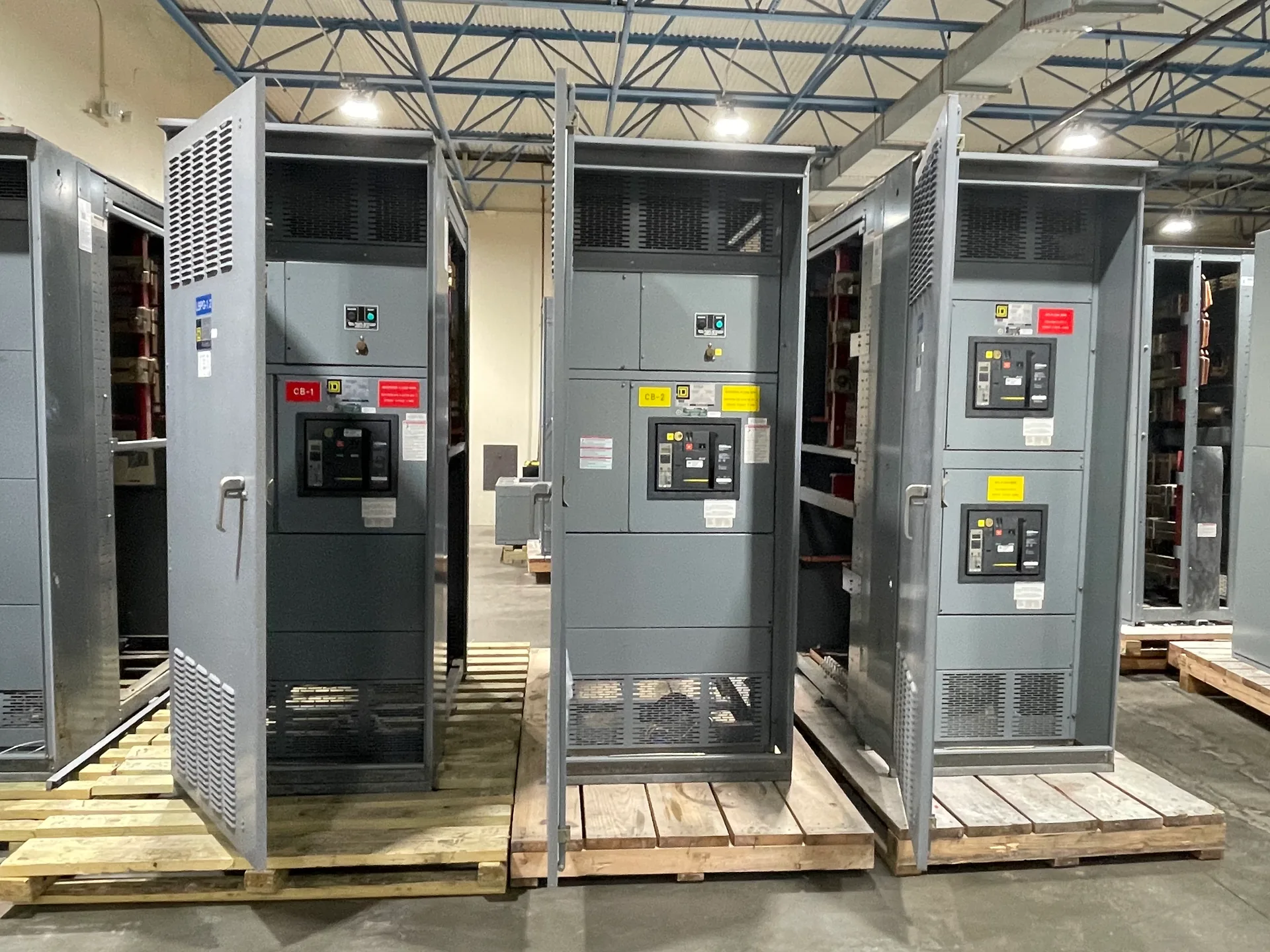
HVAC plant power distribution starts with the equipment schedule, operating sequence, and site conditions—not a one-size-fits-all lineup. Chillers, cooling towers, pumps, air handlers, and other loads can have different starting methods and operating priorities. Switchgear Builder Virginia can develop custom new switchgear for projects across the United States, with all-American components and short lead times subject to quote and verification. The project team should confirm ratings, applicable requirements, and schedule before equipment is specified.
Map Loads and Feeders
Build the distribution plan from an up-to-date one-line diagram and equipment list. Identify each chiller, condenser-water pump, chilled-water pump, cooling-tower fan, air handler, and other plant load, then record its voltage, phase, nameplate current, starting method, and intended source. Note which loads operate together, which are standby or redundant, and which must remain available during a planned shutdown. This separates essential operating paths from convenient grouping by equipment location. Confirm whether the plant is served by one incoming source, multiple sources, or a future tie arrangement; do not assume a tie can carry every load. The designer can then evaluate feeder and bus arrangements against verified demand, fault-current data, and project requirements. Clear load mapping also helps the owner compare initial capacity with future expansion without treating spare space as spare electrical capacity.
Coordinate Starters and Drives
Starting and speed-control choices influence the electrical design, so capture them before finalizing feeder and distribution requirements. Across-the-line starters, reduced-voltage starting, and variable-frequency drives can differ in starting current, control needs, harmonics, heat, and operating behavior. Those effects depend on the specific motor, equipment package, and system design; they should be evaluated with the mechanical and electrical teams rather than assumed from the equipment label. Confirm whether a drive is furnished separately or integrated into another package, and identify any bypass or alternate operating mode as a project requirement to review. Ask equipment suppliers for motor data, drive input characteristics, and control interfaces. The switchgear specification can then address the verified connection and coordination needs without implying that every starter or drive is part of the switchgear lineup. Confirm compatibility and ratings for the actual configuration.
Plan Capacity and Expansion
Capacity planning should account for the plant’s expected operating combinations, not simply add every nameplate value or rely on a general percentage allowance. The engineer should establish the applicable demand and diversity assumptions, evaluate starting and operating conditions, and verify conductor, bus, protective-device, and interrupting requirements for the project. If a later chiller or pump is anticipated, show that load in the design basis and identify whether future capacity means reserved physical space, a planned feeder position, or additional electrical capacity. These are different provisions and need separate confirmation. A vacant section does not by itself establish that the source, bus, or upstream equipment can serve added load. Review available room, access, cable routing, and shutdown constraints alongside the electrical calculations. Documenting these assumptions lets buyers compare proposals on what is actually included and what remains a future project decision.
Design for Maintenance Isolation
A maintainable layout gives operators a planned way to isolate equipment for service while preserving only the operations the system is designed to support. Map normal and standby equipment, identify the intended isolation points, and review how a chiller, pump, or fan can be taken out of service without relying on an unverified switching sequence. The electrical engineer and facility team should confirm the required arrangement, interlocks, labeling, access clearances, and any operating procedures for the specific installation. Consider whether equipment connections and feeder groupings make routine work practical, and whether a planned shutdown is acceptable for each load. Do not assume that a particular bus configuration provides uninterrupted service or safe isolation in every condition. The final documents should clearly distinguish equipment boundaries, switching responsibilities, and any conditions that require qualified personnel or additional project review.
Verify Project Requirements
Before requesting a proposal, assemble the current one-line diagram, equipment schedules, utility or source information available to the design team, site constraints, and the desired operating sequence. Confirm nominal voltage, system configuration, available fault-current data, environmental conditions, enclosure needs, and any applicable project specifications with the responsible professionals. Ratings, protective-device selection, coordination, and approvals depend on the verified installation and are subject to quote and review. For applicable low-voltage switchboards, UL 891 assemblies can be discussed when the project requires them; that standard does not apply to medium- or high-voltage switchgear. Switchgear Builder Virginia manufactures new custom equipment in the United States using all-American components and ships nationwide. Lead times are subject to quote and verification, not a delivery promise. A complete request helps the manufacturer identify open questions early and develop a configuration for the confirmed HVAC plant requirements.