
GLOSSARY / MANUFACTURER DIRECT
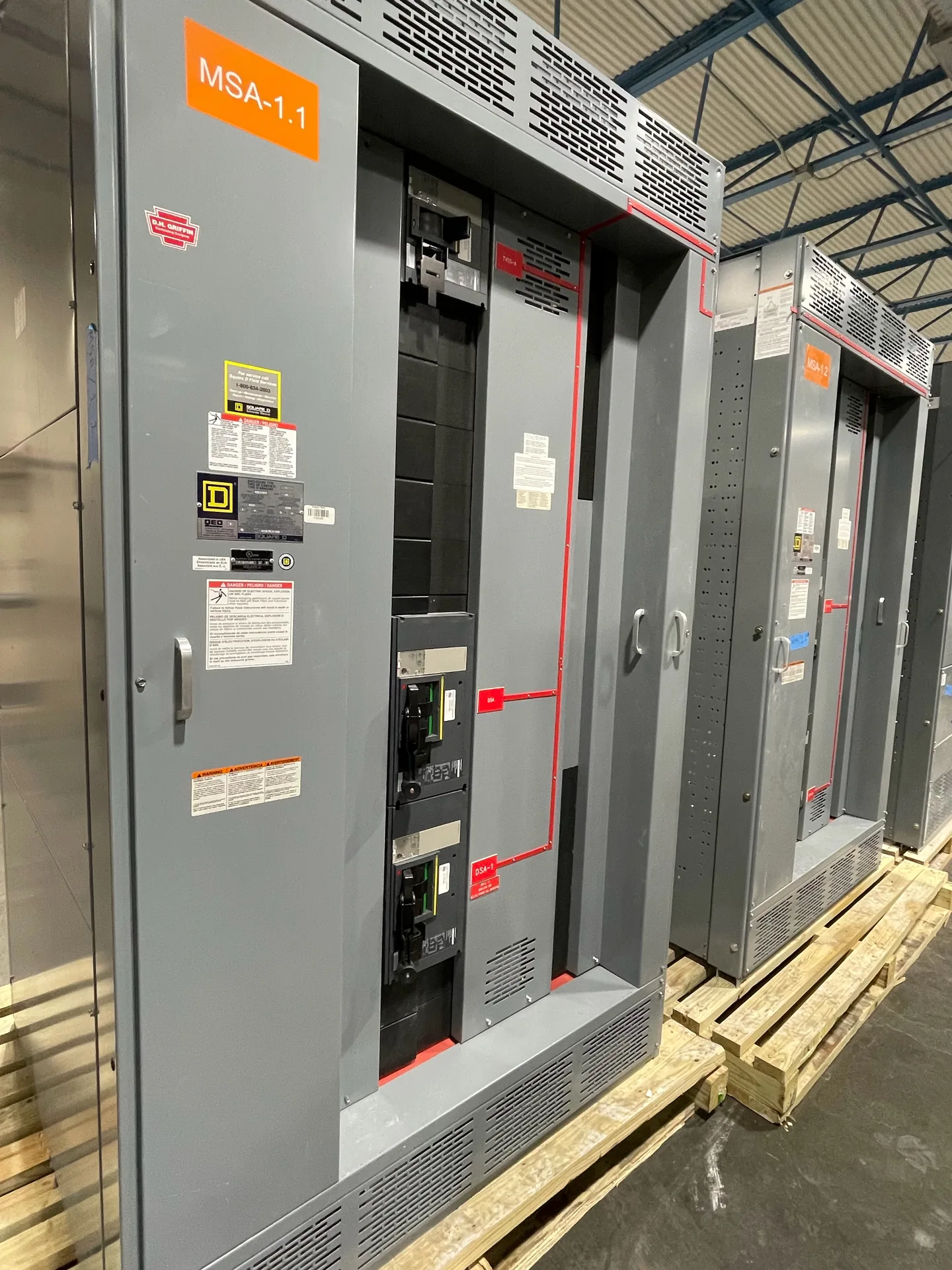
A Kirk-key interlock is a form of trapped-key interlocking: a mechanical arrangement that uses controlled key release to require a planned order of operations. The name is commonly associated with a product brand, while “trapped-key interlock” describes the broader concept. In switchgear, the arrangement may coordinate breaker operation with another device or access point, depending on the engineered sequence. For buyers planning new equipment, the key question is not simply whether a lock fits, but which operating steps must be enforced and how the sequence will work with the complete system.
The basic idea
A trapped-key interlock uses a key that is held captive until a specified mechanical condition is met. Once released, the key can operate another lock or interlock, making the next action dependent on the preceding one. For example, a system might require an operator to place a switching device in a defined position before a key becomes available for a subsequent step. The exact sequence depends on the equipment and the intended safety procedure; the key mechanism does not determine whether that procedure is appropriate. The useful distinction is between a lock that merely restricts access and an interlock designed to enforce a sequence across multiple points. A Kirk-key interlock is a brand-associated example of this general approach, not a universal name for every trapped-key system. ([sentricsafetygroup.com](https://www.sentricsafetygroup.com/us/product/type-t-interlock-2/))
How keys control sequence
In a simple arrangement, a key remains trapped while a breaker handle or other operating mechanism is in a specified state. Moving that mechanism into its intended position may allow the key to turn and release. The released key can then operate a second interlock, such as one controlling another device or an access point. More involved layouts can use transfer units that exchange one set of keys for another, but the sequence must be designed around the actual equipment and operating steps. This is a mechanical way to make certain actions conditional; it is not a substitute for the facility’s electrical safety program, operating procedures, or other protective measures. Kirk product documentation describes interlocks and transfer units as parts of sequenced applications, with configurations varying by use. ([sentricsafetygroup.com](https://www.sentricsafetygroup.com/wp-content/uploads/2026/02/type-t-kirk-01-26.pdf))
Why application details matter
The right interlock arrangement depends on what must be prevented, which devices participate, and the order operators need to follow. A designer should identify the switching devices, normal and alternate operating states, access points, key release conditions, and any required transfer steps. Mechanical fit is another practical concern: the interlock must suit the equipment’s operating mechanism and available mounting provisions. A sequence that works on paper can be confusing or impractical if keys are not clearly controlled, operating steps are ambiguous, or the hardware cannot be installed as intended. Include the interlock concept early in a new switchgear discussion rather than treating it as a last-minute accessory. Final selection, sequence details, ratings, and compatibility require project-specific review and confirmation before ordering.
Limits and coordination
A key interlock enforces only the mechanical conditions built into its arrangement. It does not independently verify every electrical hazard, establish that equipment is de-energized, or replace qualified personnel and approved work practices. Nor should a proposed sequence be assumed to match a site’s procedures simply because it resembles a familiar application. The project team should define the intended sequence, review it against the equipment design, and confirm that each key has a clear purpose and controlled destination. Where existing switchgear is involved, its actual configuration and condition must be assessed by qualified professionals before deciding whether an interlock can be integrated. Interlock details, installation provisions, and acceptance requirements can differ by equipment and project, so they should be verified rather than inferred from a product name.
Planning a new assembly
For a new low-voltage switchboard or switchgear assembly, share the one-line diagram, equipment schedule, switching sequence, and a description of any access or operating constraints during design review. Identify which device state releases each key and what action that key is meant to permit; this makes the requested logic easier to check for gaps or unintended steps. Switchgear Builder Virginia manufactures new equipment in the United States using all-American components and offers custom builds, with short lead times and nationwide shipping; schedules remain subject to quote and verification. UL 891 applies only where the assembly is an applicable low-voltage switchboard, and should not be assumed for other equipment. Whether a particular interlock, brand, mounting provision, or sequence can be included must be confirmed for the project. ([sentricsafetygroup.com](https://www.sentricsafetygroup.com/wp-content/uploads/2026/02/type-f-kirk-01-26.pdf))