
TECHNICAL GUIDES / MANUFACTURER DIRECT
Field assembly begins where factory-built sections meet at the project site. Before equipment ships, the project team should identify which joints are intended for field connection, what hardware and instructions accompany them, and who will perform and document the work. Switchgear Builder Virginia manufactures custom new equipment in the USA using all-American components, with nationwide shipping; the quoted scope and schedule require project-specific review. Shipping, assembly, installation, inspection, and acceptance are separate responsibilities unless contract documents explicitly define otherwise. Clear interface planning helps buyers coordinate the equipment package with the electrical contractor, engineer, and other parties responsible for the installation.
Identify Each Joint
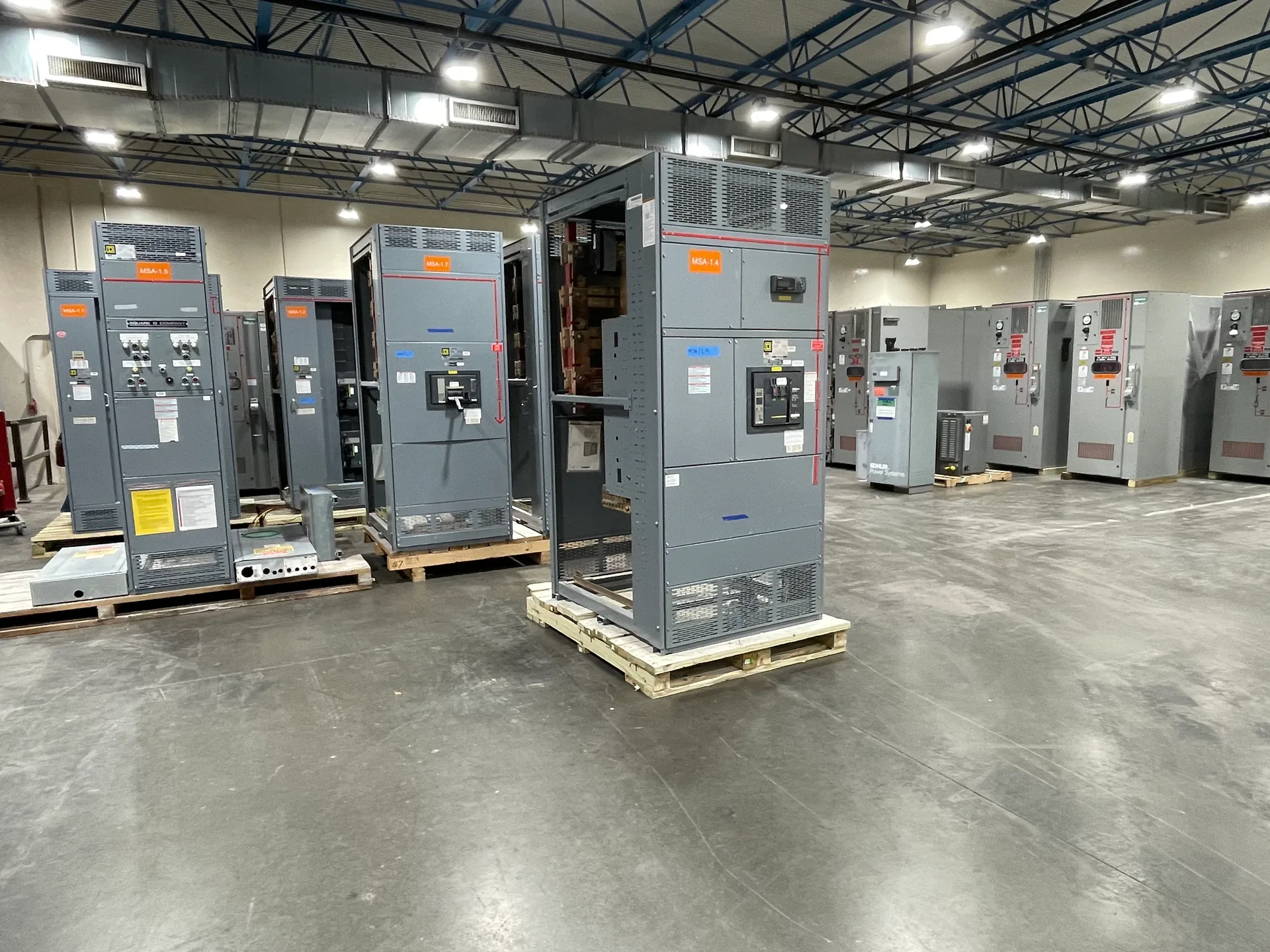
A shipping joint is a connection between sections that are separated to accommodate transportation and then joined at the site. The approved drawings and assembly instructions should show which sections separate, how they align, and what connecting parts are supplied. Buyers should confirm whether bus links, fasteners, barriers, covers, or other joint-specific items ship with each section, and how those items are identified. Do not assume that similar-looking sections use interchangeable hardware or that a joint can be assembled from generic parts. Confirm the required sequence, access clearances, lifting and positioning coordination, and any temporary protection needed before connection. The manufacturer’s documents for the quoted configuration should govern; questions or mismatches should be resolved before work proceeds. This avoids relying on field improvisation and makes the boundary between factory assembly and site work visible to all project participants.
Plan the Work Boundary
Field assembly is not automatically part of equipment supply. The purchase documents should state which sections arrive joined, which joints require site assembly, and which party provides labor, tools, supervision, and coordination. A buyer should also clarify responsibility for receiving, storage, movement into position, alignment, connection, and protection after unpacking. These tasks may involve multiple contractors, so the project schedule should identify prerequisites and handoffs rather than assume they are included in the switchgear quote. If the site has restricted access, limited laydown space, or a specific delivery sequence, communicate those conditions during quotation and confirm the resulting equipment breakdown and scope in writing. Switchgear Builder Virginia can review custom equipment requirements for quotation; schedule and scope depend on verification. Clear written boundaries help prevent gaps, duplicated effort, or an assumption that shipping a product includes field installation.
Document Torque Records
Torque records provide a traceable account of specified bolted connections completed during field assembly. The applicable equipment instructions should identify which joints require torque control, the required method or value, and any sequence or tooling requirements. Do not apply a remembered value from another lineup or substitute a general fastener chart for configuration-specific instructions. The responsible installer should use suitable, maintained tools and record the joint or location, date, method, and result in the format required by the project. If a fastener, thread, joint surface, or instruction is damaged, missing, or unclear, pause that connection and seek direction from the responsible project authority or manufacturer. Keep records with the project turnover documents and make them available to the engineer or inspector as required. The quote should clarify whether any factory documentation is supplied; field records remain tied to the party performing the work.
Coordinate Grounding
Grounding interfaces should be established from the approved drawings and equipment instructions before sections are connected. Confirm how the ground bus or other designated grounding provisions continue across shipping joints, which connectors are supplied, and what site conductors or terminations are outside the equipment package. The engineer and installing contractor should reconcile the switchgear grounding arrangement with the project design and applicable requirements; do not infer conductor size, bonding method, or connection location from appearance alone. Check that joint surfaces and hardware are prepared as directed, and document completed connections under the project’s procedures. If the delivered arrangement differs from the drawings, or a required part is absent, resolve the discrepancy before proceeding rather than modifying the equipment without authorization. These checks distinguish the factory-provided interface from site wiring and help the project team assign each grounding task to a named responsible party.
Set Inspection Responsibilities
Project documents should identify who inspects field-assembled joints, what records are required, and when inspection must occur relative to energization or concealment. Responsibilities may involve the installing contractor, engineer, owner’s representative, or an authority having jurisdiction, depending on the project; verify the actual requirements rather than assuming a particular inspection or approval applies. The equipment manufacturer’s instructions and approved drawings provide the reference for assembly, while project specifications may add documentation or review steps. Confirm how discrepancies, incomplete records, or damaged components are reported and resolved, and who authorizes continuation. A factory test or inspection, if specified and documented for the quoted equipment, is distinct from site assembly inspection and does not establish that field work has been completed or accepted. Keep the final package of drawings, instructions, torque records, grounding documentation, and inspection evidence organized for turnover. Scope and applicable documentation should be confirmed in the quote and project documents.