
TECHNICAL GUIDES / MANUFACTURER DIRECT
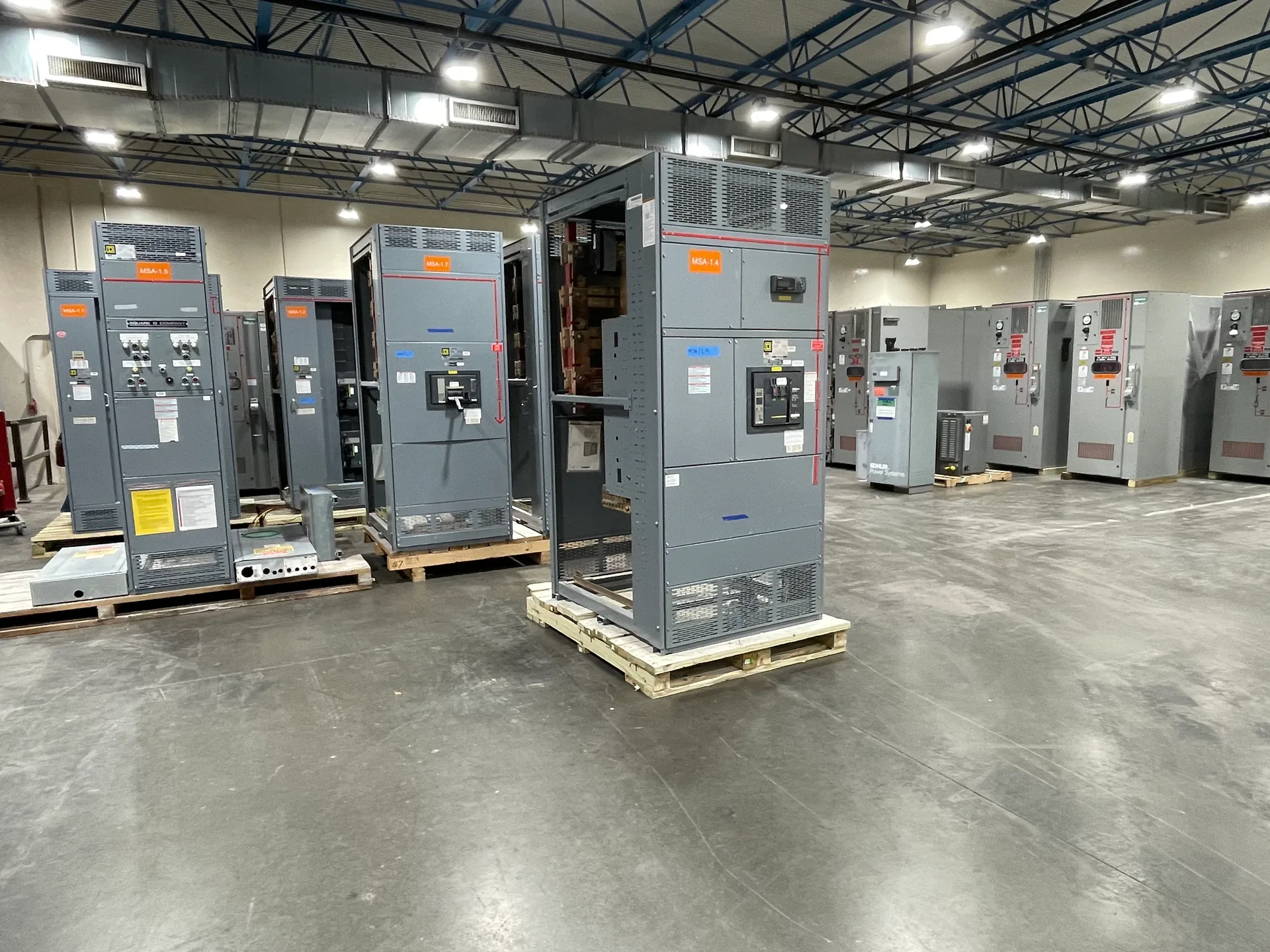
A switchgear lineup is arranged in sections, each assigned a job such as receiving power, protecting a feeder, measuring energy, or connecting bus. The sequence affects more than the one-line diagram: it influences equipment width, working access, cable paths, and how operators identify devices. Switchgear Builder Virginia manufactures custom new equipment in the USA using all-American components, with nationwide shipping. The right layout depends on the electrical design and the room it must fit. Treat section names as planning categories, not fixed dimensions or a promise that every function can be combined in one section.
Start at the Source
An incoming section is the lineup’s connection point to the upstream source. Its arrangement depends on how power enters the equipment, where conductors approach, and what disconnecting or protective devices the design requires. The main section contains the principal switching or protection function for the bus, but it may be integrated with an incoming section or placed separately; the one-line diagram and design criteria determine the appropriate arrangement. Buyers should identify source and main-device requirements early, including access needed for operation, inspection, and cable termination. These choices can influence enclosure width, depth, barriers, and the position of adjacent sections. Do not assume that a familiar section label defines a standard footprint: device selection, conductor space, and project requirements can change dimensions. Confirm the proposed arrangement against approved drawings, site measurements, and equipment specifications before release.
Plan Feeder Sections
Feeder sections distribute power from the lineup to downstream loads. Their size and sequence depend on the devices selected, conductor routing, cable entry, and the number and arrangement of outgoing circuits. A row of compact feeders may use space efficiently, while larger devices or extensive cable requirements can call for wider sections or additional room for terminations. Grouping circuits by destination or function can make schedules and field identification clearer, but the best grouping also depends on how cables reach the lineup and how operators need to access devices. Check that circuit labels, device ratings, and termination arrangements align with the electrical documents; do not infer capacity from section count alone. Early coordination can reduce drawing revisions when feeder needs change. Final dimensions, ratings, and construction details are subject to project-specific review and confirmation.
Allow for Metering
A metering section provides space for the instruments and related components specified to measure or monitor electrical quantities. The required arrangement depends on the measurement scheme, instrument locations, wiring paths, and whether the design calls for a dedicated section or metering integrated with another function. Buyers should identify what is to be measured, which documents govern the metering arrangement, and who is responsible for supplying any specified components. Access matters: readings and inspection should be practical without creating conflicts with adjacent equipment or cable space. A narrow metering section may appear efficient on a layout, but its suitability depends on the actual devices, clearances, wiring, and operating needs. Confirm details on project drawings rather than assuming that every lineup includes identical metering provisions. If the equipment is a low-voltage switchboard, verify whether UL 891 requirements apply to the specific assembly.
Use Transition Sections
A transition section connects lineup portions with different arrangements, equipment, or physical interfaces. It may be considered where the bus configuration, enclosure geometry, or connection point changes, but its purpose and construction must be established in the project design. Treat a transition as a functional space, not merely an empty filler: bus connections, barriers, cable routing, and access can affect its dimensions. Buyers should coordinate the adjoining equipment boundaries, connection details, and overall lineup sequence before drawings are finalized. If another assembly or field-installed component is involved, confirm who provides each interface and what information is needed for coordination. A transition that is too small can complicate routing; one that is unnecessarily large can consume valuable room. The right balance depends on verified equipment details and site constraints, so review dimensions and interfaces with the project team.
Position Tie Sections
A tie section connects bus sections through a specified switching arrangement, where the electrical design calls for that function. Its position can affect how the lineup is divided, where operators reach the device, and how incoming and feeder sections are grouped on either side. The tie’s intended operating scheme, interlocking requirements, and relationship to the main devices must come from the project documents; the section name alone does not establish those details. Consider working access and device handling alongside the one-line diagram, cable routing, and available room. A centered tie may simplify visual grouping in some layouts, while other designs may place it elsewhere to suit the electrical arrangement. Verify that the proposed section order, dimensions, and interfaces match approved requirements. Switchgear Builder Virginia can develop custom new equipment layouts; schedules and ratings remain subject to quote and verification.