
PRODUCTS / MANUFACTURER DIRECT
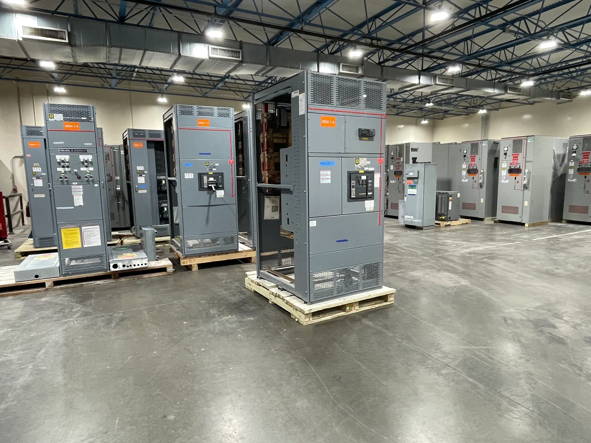
A distribution switchboard organizes an incoming electrical supply into outgoing feeder circuits for building systems and equipment. Planning one means balancing the loads served, protection needs, available space, and room for future changes. Switchgear Builder Virginia manufactures custom switchboards in the USA using all-American components, with nationwide shipping. The right arrangement depends on project details, so feeder counts, ratings, schedules, and applicable requirements must be established and verified for the specific quote.
Map the power path
Begin with the source feeding the switchboard and identify each downstream feeder, its destination, and the load it serves. This map helps the design team understand how power is distributed and where isolation or protective devices may be needed. Grouping similar loads can make the lineup easier to review, but grouping should not obscure which circuits supply critical equipment or separate areas. Provide available utility or upstream equipment information, project drawings, and the intended operating arrangement for review. The source configuration, voltage, current, and fault conditions are project requirements to verify, not assumptions to carry over from another installation. A clear one-line diagram gives the manufacturer and project team a common basis for checking the incoming section, outgoing feeders, and interfaces with connected systems before the equipment layout is finalized.
Set feeder protection
Each outgoing feeder needs protection selected for the connected load and the electrical conditions at its point of connection. Depending on the design, buyers may compare breaker types, trip functions, or other protective-device options; availability and suitability must be confirmed for the project. Coordination with upstream and downstream devices can affect device selection and settings, so the reviewing engineer should identify the intended coordination approach and provide relevant system data. Do not select protection solely by matching a load’s nameplate current: starting behavior, conductor constraints, available fault current, and the equipment served may also influence the specification. Where continuity is important, ask how a fault on one branch is expected to affect adjacent feeders. Final device ratings and settings require verification against the project design and applicable requirements.
Choose feeder count
Feeder count should reflect the circuits planned for initial operation, plus any carefully defined future circuits the project expects to add. More ways can preserve flexibility, but they also use physical space and may affect cost, arrangement, and the size of the enclosure or lineup. Unassigned positions are not automatically usable spare capacity: the project must specify whether future provisions include a space, bus connection, protective device, or another defined arrangement. Distinguish installed feeders from planned spares in the schedule, and identify the expected load or purpose of each. This lets the design review consider not just the number of outgoing circuits, but how each circuit fits the electrical and physical plan. The final feeder count, device requirements, and provision for future work are subject to quote and verification.
Plan spare capacity
Spare capacity can refer to electrical loading, extra feeder positions, or physical room for later equipment, and these are different design considerations. State which kind of reserve the project needs and how it will be evaluated. A switchboard with empty spaces may still have limits imposed by bus capacity, service conditions, enclosure dimensions, or the arrangement of protective devices. Conversely, specifying larger capacity without a defined load-growth basis can add size without delivering useful flexibility. Share the anticipated load profile and any documented expansion plans so the design team can review the requested margin. Future additions may require new engineering review and must not be assumed to fit an existing arrangement without verification. Ratings, spare provisions, and compatibility with future equipment are established for the specific project rather than inferred from a general product description.
Size the sections
Section sizing affects how incoming equipment, bus, protective devices, cable connections, and access needs fit together. The layout must account for project-specific conductor entry and exit directions, termination space, equipment dimensions, and the surrounding installation. Provide drawings and interface details early, especially when the switchboard must align with other electrical equipment or fit within a defined room. A compact arrangement may reduce footprint, while added separation or working space can make installation and maintenance planning more practical; the applicable design and site requirements determine what is acceptable. Confirm dimensions, access, and connection details with the project team before release for manufacture. Switchgear Builder Virginia offers custom builds and short lead times, but actual schedules depend on the quoted scope and must be confirmed. Applicable UL 891 assemblies are available where appropriate and subject to verification.