
PRODUCTS / MANUFACTURER DIRECT
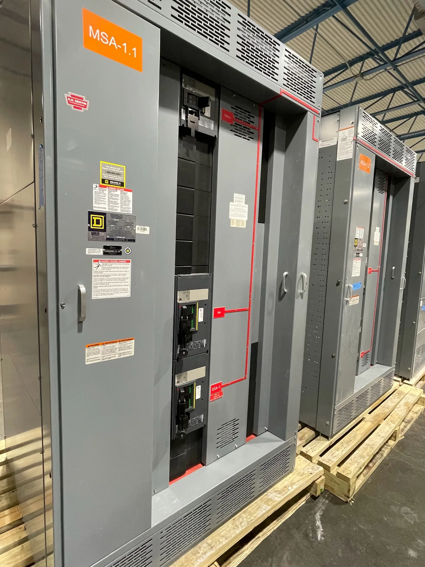
A generator connection switchboard provides a defined point for connecting generator output to a building’s electrical distribution system. The design must match the generator, utility arrangement, connected loads, and operating sequence—not just the generator’s nameplate. Switchgear Builder Virginia builds custom switchboards in the USA with all-American components and ships nationwide. For applicable low-voltage switchboards, UL 891 assemblies may be specified; applicability and project requirements need verification. Final configuration, ratings, scope, and schedule are subject to project review and quote.
Define the Generator Connection
Start with how generator power reaches the switchboard: one generator or several, the number of connection points, and whether conductors terminate at lugs, a breaker, or another specified interface. These choices affect compartment space, cable routing, access, and coordination with the generator package. Provide the generator’s voltage, phase, frequency, output rating, and available fault-current information for review; do not assume a connection is suitable from kW alone. The switchboard design also needs the intended load and operating mode, such as standby or parallel operation, because those requirements can change the protective and control arrangement. Confirm the generator manufacturer’s connection details and the engineer’s one-line diagram before fixing the scope. A custom build can address a project-specific layout, but ratings and component selections remain subject to quote and verification.
Plan Isolation and Service Boundaries
Isolation defines which equipment can be separated from the generator connection and how that boundary fits the overall system. Buyers should clarify whether the generator feeder has a dedicated disconnecting means, whether a generator output breaker is furnished with the generator or switchboard, and what terminals or conductors are included at the interface. The answer affects compartment arrangement, cable access, and responsibility between equipment suppliers. Specify the intended maintenance and operating boundaries in the project documents rather than relying on a generic label such as generator connection switchboard. Also confirm whether the switchboard is indoors or outdoors and what enclosure requirements apply; those details can affect construction and access. Isolation provisions must be coordinated with the project design and applicable requirements. No live-work procedure should be inferred from the equipment description; installation and operation belong to qualified personnel following approved project documentation.
Coordinate Source Interlocks
Source interlocks help prevent an unintended operating condition, but the right arrangement depends on how the generator and normal source are connected. A project may require mechanical interlocking, electrical permissives, control logic, or a coordinated combination; these approaches are not interchangeable without reviewing the intended sequence. State whether the system is open transition, closed transition, or another arrangement specified by the engineer, and identify which device initiates and controls transfer. If paralleling is intended, describe the operating modes and required coordination rather than assuming a basic interlock provides synchronization or load sharing. Confirm the interface with any automatic transfer equipment, generator controls, and upstream devices. Provide a sequence of operation and identify what signals are furnished by others. Interlock design, ratings, and control functions should be verified against the one-line diagram and project requirements before release for manufacture.
Specify Protective Devices and Controls
Protective-device selection depends on system voltage, available fault current, conductor details, generator characteristics, and coordination requirements. Share the project’s fault-current study or design basis, device settings requirements, and upstream and downstream equipment information for engineering review. Do not treat an interrupting rating, trip function, or trip setting as established by a general product description. Controls may include status indication, alarms, breaker operation, or interface points, but each function should be listed with its source, destination, and required behavior. Identify whether control power, metering, communications, or remote signals are included, and note items furnished by the generator supplier or others. This avoids gaps and duplicate scope. Component choices and ratings are options to verify for the specific project; final suitability depends on the approved design and applicable requirements. Where applicable, UL 891 requirements for a low-voltage switchboard should be confirmed during scope review.
Clarify Transfer Equipment Scope
A generator connection switchboard does not, by itself, establish that transfer equipment is included. Automatic transfer switches, bypass-isolation features, paralleling controls, generator controls, and utility service equipment may be separate devices or separate supplier scopes. Ask for a clear equipment list and one-line diagram showing the normal source, generator source, transfer function, and load connection. Confirm who provides transfer logic, control wiring between enclosures, field terminations, commissioning, and any required testing or approvals; these are project-specific scope questions, not automatic inclusions. Switchgear Builder Virginia can review custom-build requirements, with schedule and ratings subject to quote and verification. Direct USA manufacturing, all-American components, and nationwide shipping are company capabilities; shipping does not establish an installation location or local office. Provide drawings, load data, interface details, and sequence requirements so the proposed assembly can be evaluated against the actual project.