
PRODUCTS / MANUFACTURER DIRECT
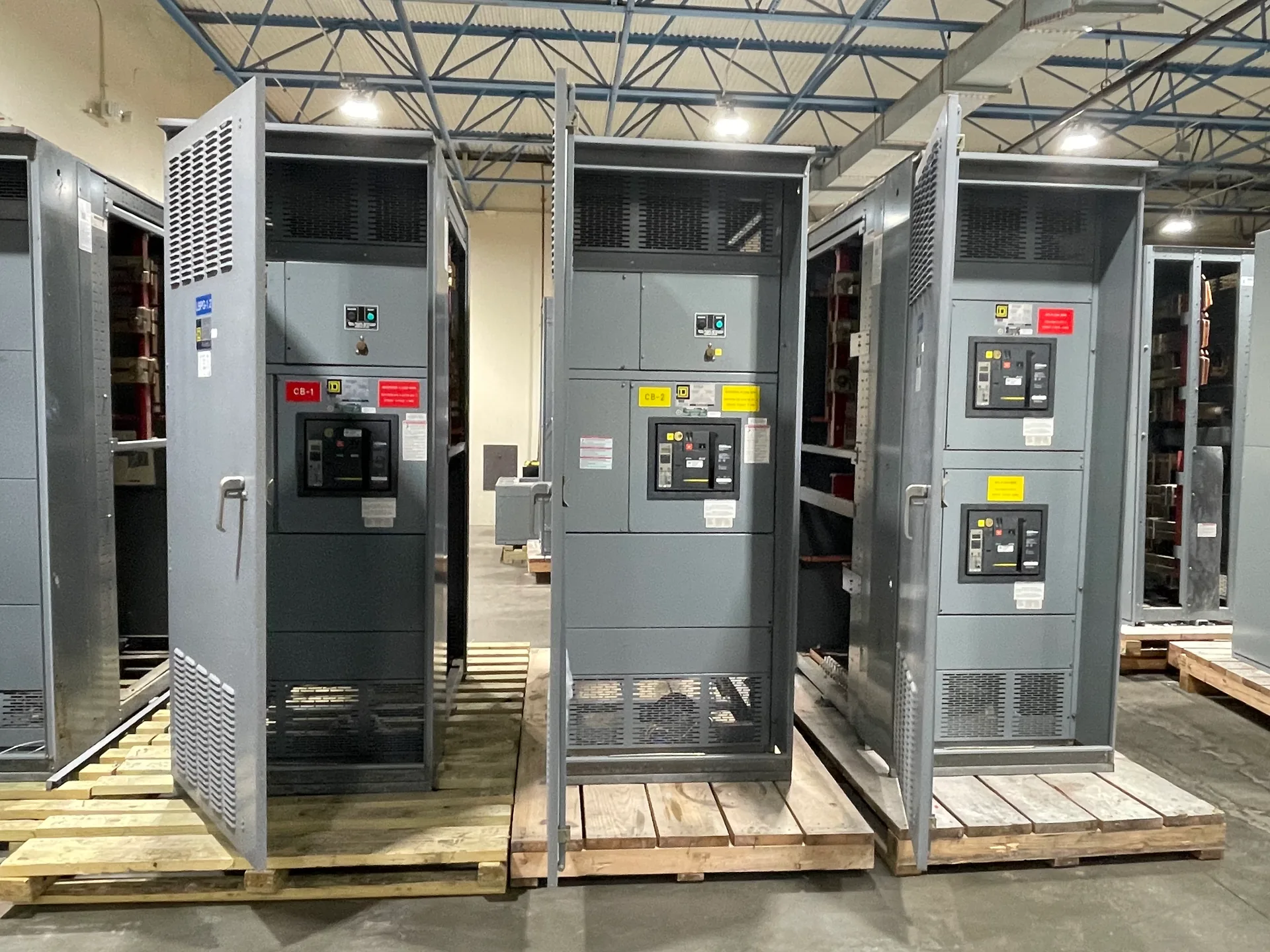
Primary selective switchgear connects two primary power sources through switching equipment arranged to serve a common load. Its value depends on more than having two incoming sources: the design must define which source normally carries the load, how transfer is initiated, and what prevents an unsafe or unintended connection. Switchgear Builder Virginia manufactures custom new switchgear in the USA using all-American components, with nationwide shipping and short lead times subject to project scope and quote. The source voltages, utility arrangement, protection scheme, and required equipment ratings must be established and verified for each project before a configuration or schedule can be confirmed.
Define the source arrangement
Start with a one-line diagram showing both primary sources, incoming switching devices, bus sections, tie points, transformers, and downstream loads. The diagram should identify whether the sources come from separate utility feeders, separate substations, or another arrangement; two cables do not necessarily represent independent sources. Confirm each source’s nominal voltage, available fault current, grounding method, and operating limitations with the responsible utility and project engineers. Also establish whether both sources may remain energized at the switchgear at the same time. These details affect insulation and interrupting requirements, equipment layout, and the permitted switching sequence. A primary selective arrangement is not automatically a closed-transition or paralleling system. If simultaneous source connection is not intended or approved, the design and controls should make that operating boundary clear. Provide the actual utility requirements rather than relying on a generic diagram or assumed feeder characteristics.
Choose the transfer sequence
Write the normal and alternate operating states in plain terms: which source supplies the load, what condition prompts transfer, and what steps return the system to normal. Decide whether transfer is manual or automatic and whether a transfer may occur only after the preferred source is confirmed unavailable. Specify how the system behaves if the alternate source is unavailable, a breaker fails to operate, or control power is lost. Define any intentional delay, operator action, alarm, or reset requirement with the engineering team. Transfer timing should reflect the load’s ability to ride through an interruption and the utility’s operating rules; it should not be selected from a generic catalog description. Also state whether transfer is open transition, with the first source disconnected before the second connects. These requirements let the manufacturer evaluate switching devices, control logic, indication, and wiring without assuming that every two-source installation needs the same sequence.
Coordinate interlocks and controls
Interlocks help enforce the approved operating sequence, but their purpose must be specified rather than left implicit. Identify which switching positions must be mutually exclusive, which operations require an operator key or permissive, and whether electrical or mechanical interlocking is required. If closing a tie or alternate-source device could connect the sources together, the design should address that condition explicitly and coordinate with utility rules. Describe the intended response to a control-power failure, a stuck device, or an inconsistent position indication. Confirm how local controls, remote commands, status contacts, alarms, and any supervisory system will interact. Interlocks do not replace sound protection coordination or operating procedures, and a control scheme cannot establish that two utility sources are independent. The project documents should state which positions and events are monitored, what indications operators need, and who is responsible for reviewing the final logic and sequence before equipment is released.
Set protection and ratings
Protection must be coordinated across the sources, incoming devices, bus, tie, transformers, and downstream equipment. Provide available fault-current data for each source and clarify whether the values differ by operating state. The engineering review can then establish required equipment ratings, protective-device functions and settings, and coordination with upstream utility protection. Do not assume that a device’s voltage class or continuous-current value alone establishes suitability; interrupting duty, short-time withstand, insulation requirements, and the complete assembly configuration also matter. Identify any project-specific monitoring, metering, or protection functions as requirements to evaluate. Ratings and settings are subject to engineering review and quote verification, and the final design should be checked against the applicable project documents and authority requirements. For primary selective switchgear, the protection scheme must account for both normal and alternate supply paths, including the consequences of changing source or bus configuration.
Prepare a buildable specification
For a useful quotation, share the one-line diagram, utility service information, load data, site and environmental conditions, required enclosure arrangement, control-power source, and applicable project specifications. Include the preferred transfer sequence, interlock requirements, protection responsibilities, metering needs, and any interface with existing equipment. Identify which details are fixed and which may be proposed for engineering review. Switchgear Builder Virginia can develop a custom new-equipment configuration around verified project requirements; component selection, ratings, schedule, and scope remain subject to review and quote. The company manufactures in the USA using all-American components and ships nationwide. Short lead times may be available, but timing depends on the confirmed design and order requirements and is not promised until addressed in a quote. Clear documents reduce avoidable assumptions and help the project team compare proposals on the same operating sequence, protection scope, and source arrangement.