
SERVICES / MANUFACTURER DIRECT
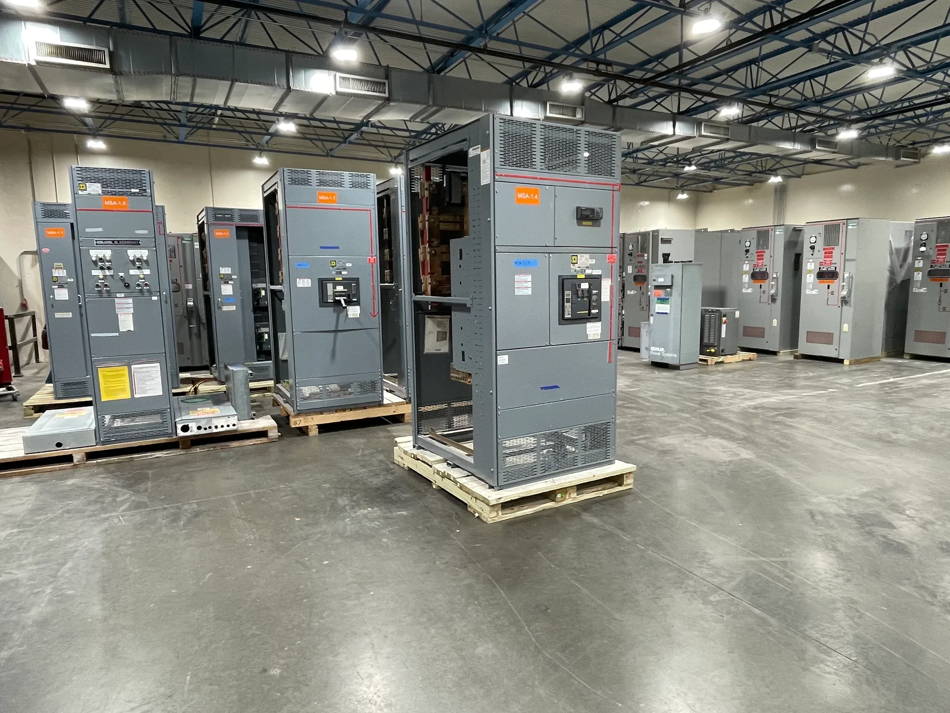
Automatic transfer switch integration begins with a clear account of the normal source, alternate source, served loads, and the equipment arrangement around them. A standalone ATS and an ATS incorporated into a switchboard lineup can serve related functions, but they present different space, wiring, coordination, and maintenance questions. Switchgear Builder Virginia manufactures new custom switchgear in the USA using all-American components, with nationwide shipping and short lead times subject to project scope and quote. The practical starting point is a coordinated set of drawings and requirements—not an assumed rating, control sequence, or delivery schedule.
Map Sources and Loads
Identify each normal and alternate source by equipment tag, voltage, phase, frequency, available capacity, and connection point, then confirm those details against current one-lines and source documentation. Describe which loads transfer, which remain on their original source, and whether loads are grouped by priority or operational function. List expected demand, starting characteristics, and any load shedding or sequencing needs for engineering review; do not treat a nameplate value as proof of system capacity. Also clarify whether both sources may be available at once, how the alternate source is initiated, and what conditions permit transfer and retransfer. These answers inform ATS selection and the surrounding switchgear arrangement, but final ratings and control behavior require project-specific verification. For a new lineup, provide available fault-current information and upstream protective-device details so qualified reviewers can assess compatibility and coordination.
Choose Standalone or Lineup
A standalone ATS is a separate assembly connected to the sources and load, while an integrated arrangement places the transfer equipment within a broader switchboard lineup. Standalone construction may simplify physical separation and equipment replacement, but it can require additional floor space, feeder routing, and coordination between enclosures. Lineup integration can consolidate distribution and provide a more unified arrangement, but section dimensions, access, heat, cable entry, and future maintenance clearances need careful review. Neither choice is automatically smaller, simpler, or more serviceable; the site layout and operating plan decide the tradeoff. Document room dimensions, conduit or bus connections, front or rear access expectations, and adjacent equipment interfaces. If a low-voltage switchboard is involved, UL 891 applicability must be confirmed for the specific assembly and scope; it does not establish an ATS rating or cover medium- or high-voltage equipment.
Define Controls and Sequence
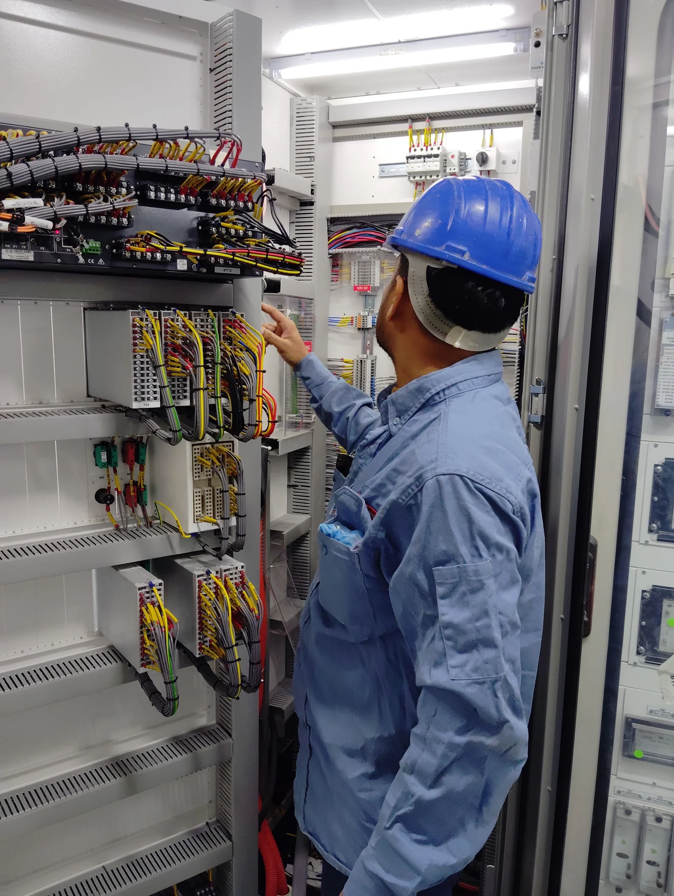
Write the intended sequence in observable steps: how loss or unacceptable quality of the normal source is recognized, how the alternate source becomes available, when transfer occurs, and what conditions permit retransfer. State whether transfer is open transition or another specified method, and identify any required time delays, engine-start contacts, alarms, test functions, and remote status points for review. A generator connection should include the generator controls interface and the signal responsibilities of each device; do not assume those functions are included in an ATS or switchgear package. Clarify who supplies control wiring, communicates with the generator vendor, and validates the sequence during project testing. Where loads cannot tolerate an interruption, identify that requirement early so the engineer can assess an appropriate transfer approach. Final control logic, settings, and interfaces must be documented and verified against the selected equipment and system design.
Resolve Interlocks and Bypass
Describe the required safeguards that prevent unintended source paralleling, including the intended switching method and any mechanical or electrical interlocking requirements. The design team should confirm how the selected equipment prevents prohibited operating states; do not rely on a general statement such as “interlocked” without identifying the devices and sequence involved. If bypass-isolation capability is required, specify why it is needed, who must operate it, and whether continuity during ATS inspection or replacement is an operational objective. Bypass arrangements can add components, space, connections, and operating steps, so weigh their maintenance benefit against complexity and ensure the proposed configuration matches the project’s requirements. Identify any preferred isolation points and document normal, emergency, test, and maintenance states for qualified review. Equipment-specific interlock details and bypass functions are options or design requirements to confirm, not features to assume from a product category.
Build a Complete Package
A useful request package includes the one-line diagram, load schedule, source and generator information, available fault-current data, protective-device details, control narrative, interface list, room layout, cable-entry preferences, and required bypass or maintenance functions. Mark unresolved items plainly so they can be addressed before fabrication documents are finalized. Ask the project team to review dimensions, connection points, ratings, control responsibility, and applicable approval or inspection requirements; verification depends on the project and selected assembly. Switchgear Builder Virginia can develop a custom new-equipment scope from documented requirements, with schedules and ratings subject to quotation and verification. Short lead times may be available, but timing depends on the final scope and schedule confirmation. Nationwide shipping is available. Clear submittals help distinguish an ATS supplied as a separate unit from transfer equipment coordinated within a new switchboard lineup and reduce avoidable interface assumptions.