
SERVICES / MANUFACTURER DIRECT
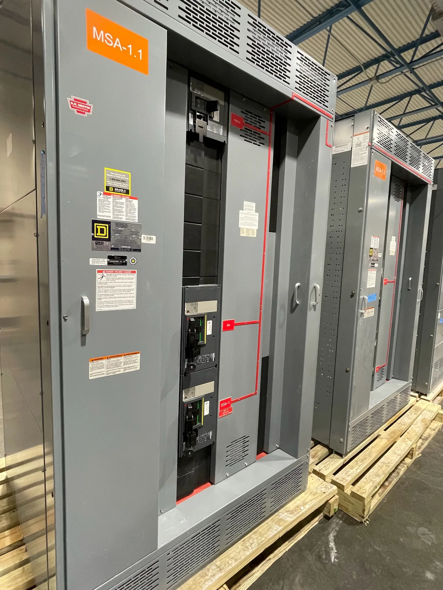
Service entrance equipment assembly defines how incoming utility power is disconnected, measured, grounded, and handed off to a building’s electrical distribution. For commercial buyers, the main task is coordinating the equipment boundary with the utility, engineer, installer, and authority having jurisdiction before drawings are finalized. Switchgear Builder Virginia manufactures new custom switchgear in the USA using all-American components, with nationwide shipping and short lead times subject to scope and quote. Assembly details, available ratings, schedules, metering provisions, and applicable UL 891 requirements must be confirmed for the project; this page does not establish a particular approval or rating.
Define the service boundary
Start by documenting where utility-owned equipment ends and customer-owned equipment begins. That boundary affects the service disconnecting means, metering arrangement, enclosure responsibilities, and who supplies or approves each interface. Give the design team the service voltage, phase, available fault-current information, conductor entry direction, and expected number of service disconnects, then verify those details against project documents and utility requirements. Do not treat a general equipment description as a complete design. The engineer and utility should resolve whether the assembly is service equipment, what devices are required at the service, and how downstream distribution connects. Those decisions can change the lineup width, bus arrangement, compartment access, and coordination with adjacent equipment. A custom build can be scoped around verified project needs, but ratings, dimensions, and lead time remain subject to drawing review and quote.
Coordinate disconnecting means
The service disconnecting means must be selected and arranged for the approved one-line diagram, service capacity, operating needs, and applicable project requirements. Buyers should identify the number and type of disconnects, expected load, feeder destinations, and any planned future spaces before requesting a quote. Breaker-based and switch-based arrangements involve different operating and protection considerations; the appropriate choice depends on the engineer’s design and verified equipment ratings, not a generic preference. Confirm short-circuit and interrupting requirements, enclosure configuration, operator access, and provisions for safe isolation through the project’s qualified design and review process. Also check whether the proposed assembly’s footprint and cable space fit the room layout and installation route. These are scope questions, not assumptions that a particular feature or rating comes standard. Clear answers early reduce drawing changes and help align the equipment with the intended service and distribution scheme.
Grounding and bonding interfaces
Grounding and bonding details need to be coordinated with the service arrangement, building grounding design, and the utility’s requirements. Provide the project’s documented grounding approach and identify the intended connection points for grounding and bonding conductors, rather than relying on a broad equipment label to settle the design. The engineer should determine which conductors and connections belong at the service equipment and how the downstream system is treated. Buyers should also flag conductor sizes, entry locations, available space, and any specified terminals or lugs for review. These details affect internal layout and connection access, so late changes can complicate the assembly and field installation. Verify that drawings show the required interfaces and that the selected equipment configuration supports them. No single arrangement should be assumed from this page: site conditions, system design, adopted code requirements, and utility rules must be checked for the specific project.
Metering and utility review
Metering is often the most utility-specific part of a service entrance scope. Before specifying compartments, windows, instrument transformers, or meter provisions, obtain the serving utility’s current requirements and confirm who supplies, installs, and approves each item. Utilities may prescribe access, sealing, working clearances, compartment dimensions, or an arrangement that differs from a project’s initial concept. Submit the proposed one-line diagram and relevant equipment drawings through the project’s review process before treating a configuration as settled. Identify whether metering is direct or instrument-transformer based only after the utility and engineer confirm the arrangement. A quoted assembly can be configured to documented requirements, but utility acceptance is not implied by a quote or a drawing review. Record review comments and approved revisions so procurement, installation planning, and field coordination reference the same configuration. Verify all rating and schedule details with the final scope.
Build scope and verify documents
A useful request for pricing includes the one-line diagram, service data, utility criteria, metering requirements, site dimensions, cable entry information, and the project’s required equipment ratings. Include applicable drawing and submittal milestones, but treat schedules as quote-specific rather than assumed delivery dates. For low-voltage switchboards where applicable, UL 891 assembly requirements can be addressed during scope review; that reference does not establish a rating, listing, or approval for every configuration. Ask the manufacturer to identify open items, assumptions, and options in the proposal, then review drawings against the engineer’s documents and utility comments before release. Confirm shipping destination and receiving constraints as part of planning. Switchgear Builder Virginia manufactures new custom assemblies in the USA and ships nationwide. Final ratings, features, schedule, and compliance details are subject to quote, project documentation, and verification by the responsible design and review parties.