
SERVICES / MANUFACTURER DIRECT
Metering integration starts with the questions that shape the switchboard layout: where measurements are taken, which loads or sources must be visible, what accuracy the application requires, and who needs the data. Switchgear Builder Virginia manufactures new custom switchgear in the USA using all-American components, with nationwide shipping and short lead times subject to quotation and verification. Metering instruments, current transformers, communications, and utility interfaces are project-specific options, not assumed features. Define requirements early, then confirm equipment suitability, utility acceptance, and applicable ratings against the project documents before release.
Choose the Measurement Point
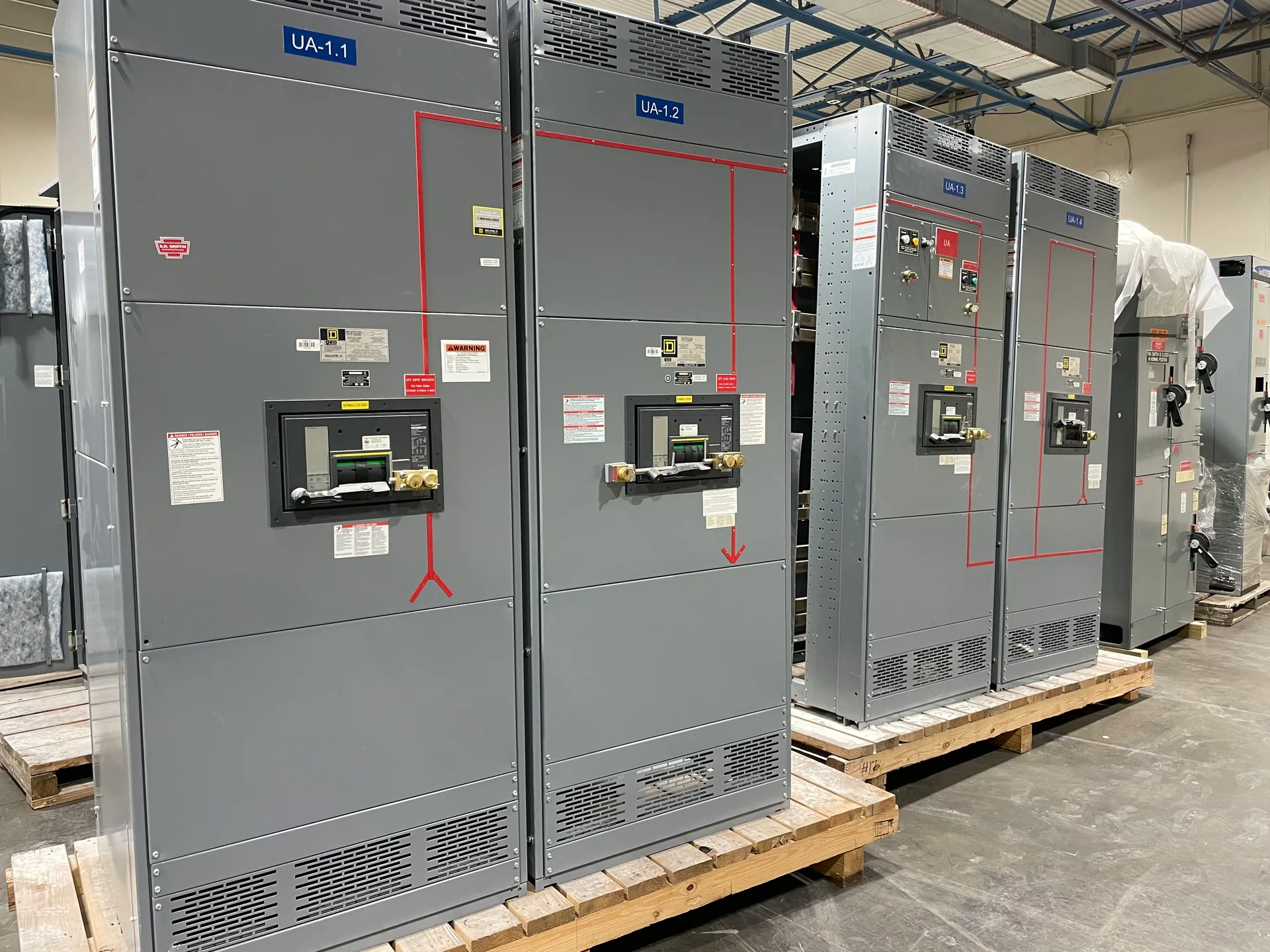
Meter location determines what the displayed or transmitted values actually represent. A meter placed on the incoming service may show total facility demand, while one downstream of a distribution point may isolate a building area, process, or major load. If the project includes multiple sources, such as utility and generator supplies, clarify whether the design needs separate readings, source status, or a defined point of common measurement. Also identify who will read the meter and whether the display must be accessible from the front of the assembly. These choices affect compartment space, wiring paths, visibility, and coordination with other devices. Provide one-line diagrams and a clear measurement intent during quotation. The proposed arrangement, instrument locations, and any utility-controlled meter space should be reviewed with the project engineer and serving utility before drawings are approved.
Specify Current Transformers
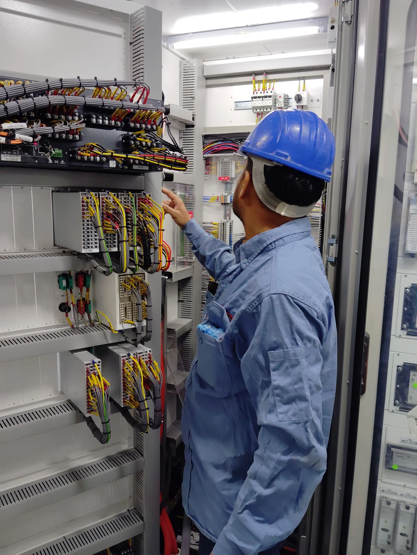
Current transformers, or CTs, scale conductor current for metering inputs. Their ratio should follow the expected operating range and the meter’s input requirements, not simply the largest current shown on a nameplate. Oversizing a ratio may reduce useful resolution at ordinary loads; choosing too small a ratio may constrain the intended measurement range. Confirm primary and secondary values, phase arrangement, conductor dimensions, available mounting space, and whether metering is required on each phase. CT burden and accuracy class also need to suit the connected meter and wiring arrangement. These are engineering selections, not interchangeable catalog details, and final values must be checked against drawings, specifications, and selected instruments. Identify any utility-prescribed CT arrangement separately from owner monitoring needs. Switchgear Builder Virginia can consider specified CTs as part of a custom new assembly, with selection and fit subject to quote and technical verification.
Set Accuracy Requirements
“Required accuracy” needs context. Billing or revenue-related measurement may be governed by the utility’s metering standards and approved equipment, while operational monitoring may prioritize trend visibility, load balancing, or energy management. The meter’s stated accuracy alone does not establish the accuracy of the complete measurement chain: CT characteristics, wiring, installation, instrument setup, and operating range matter too. State the intended use, required accuracy class if specified, measurement range, and any project or utility criteria. Avoid treating a general monitoring meter as acceptable for billing purposes unless the utility confirms that application. Where readings support energy allocation or internal reporting, document the desired precision and how data will be used. The selected device and CT combination should be checked against those requirements before release. Any testing, calibration, listing, or approval expectations should be identified in the project documents and confirmed for the proposed equipment rather than assumed.
Plan Communications and Data
A meter can provide a local display, remote data, or both, depending on the selected instrument and system design. Before choosing a communications option, identify the receiving system, protocol, network owner, connection point, and data needed. A facilities team may want demand and energy values, while a building management or supervisory system may also need alarms, status, or power-quality information. Confirm whether the project expects serial wiring, Ethernet, pulse output, or another interface; compatibility cannot be inferred from the word “communications.” Clarify who supplies network cabling, configuration, gateways, and software integration, and whether cybersecurity or network-segregation rules apply. These boundaries help avoid a meter that produces data the site cannot use. The quotation and drawings should identify the proposed meter and interfaces, while final interoperability, programming, and commissioning responsibilities remain subject to project scope and verification.
Coordinate Utility Interfaces
Utility requirements can determine meter position, enclosure access, CT placement, test provisions, wiring, and review milestones. Requirements vary by serving utility and service arrangement, so do not assume that a standard switchboard layout will be accepted. Share the applicable utility service manual, metering detail, and written project requirements before equipment drawings are finalized. Confirm who furnishes utility-controlled meters or related components, who installs and terminates conductors, and whether utility review or inspection is required before energization. If the utility specifies a separate metering compartment or an arrangement outside the switchboard, show that boundary clearly in the one-line and equipment documents. Utility acceptance must be confirmed for each service; manufacturer preparation does not substitute for utility approval. New switchboard configurations, including applicable UL 891 assemblies, are subject to design review, quote, ratings verification, and the requirements applicable to the specific project.