
SERVICES / MANUFACTURER DIRECT
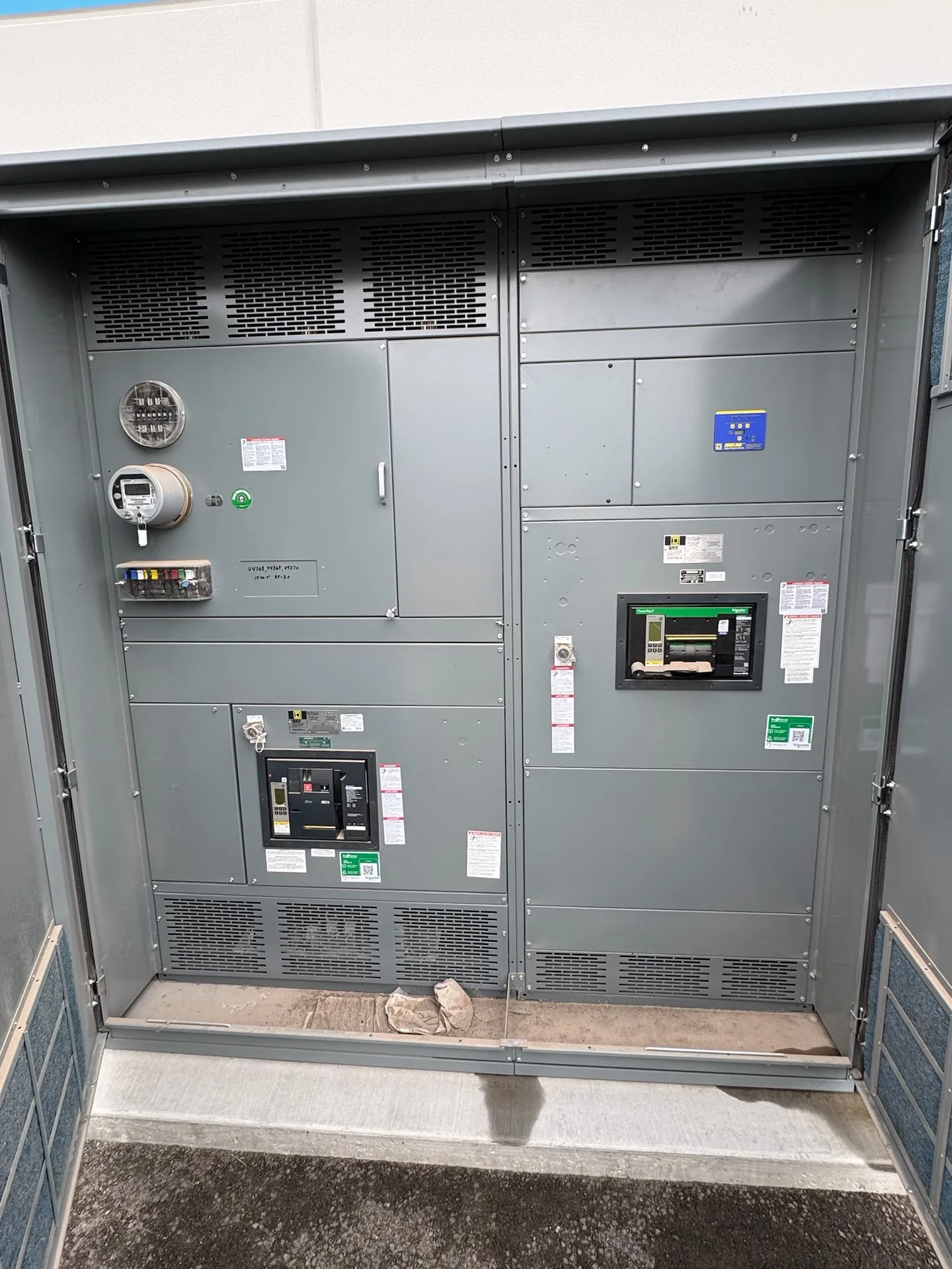
Adding a switchgear section is an engineering and integration decision, not simply a matter of matching cabinet dimensions. Switchgear Builder Virginia manufactures new custom equipment in the USA using all-American components, with nationwide shipping and short lead times subject to quote and verification. Before specifying an addition, document the installed lineup, intended loads, available space, and applicable system ratings. The existing equipment’s manufacturer, model, age, and condition can affect whether a practical interface can be developed. An assessment should identify what is known, what needs confirmation, and which design choices require coordination with the project engineer and equipment suppliers.
Start With the Existing Lineup
Collect clear equipment records before defining the new section: nameplate information, approved drawings, one-line diagrams, bus details, and available installation and maintenance records. Confirm the lineup manufacturer and series rather than relying on appearance; cabinets that look similar may use different bus arrangements, barriers, connections, or control interfaces. Identify the section’s intended position and whether it will extend an end, fill a former opening, or connect through another arrangement. Record the installed equipment’s age and any field changes, since drawings may not reflect the lineup as it stands today. Have qualified project personnel review documentation and site conditions; do not assume an unverified dimension or rating. These records help distinguish a feasible custom interface from a design that needs broader lineup changes, additional engineering, or a different equipment arrangement.
Verify Capacity and Fault Duty
Spare capacity is more than an empty breaker position. The review should establish the existing bus rating, expected demand, proposed load, protective-device requirements, and the system’s available fault current at the relevant connection point. Check whether the intended section and associated devices can be specified for the project’s required conditions, and coordinate protection with the responsible electrical engineer. Do not infer fault withstand or interrupting capability from cabinet size, a neighboring device, or a general product description. Ratings depend on the selected configuration and must be verified for the application. Changes to source equipment, transformers, conductors, or protective settings can affect the study assumptions, so use current project information. A new section’s rating and interface are subject to engineering review and quote; an assessment does not itself establish suitability or approval.
Map the Bus Interface
The bus connection is a key compatibility question. Document bus material, arrangement, phase orientation, dimensions, bracing, insulation, joints, and the location of connection points when records or authorized inspection can establish them. Also identify barriers and clearances that influence how the proposed section meets the installed lineup. Matching nominal voltage or width does not prove that sections can connect safely or mechanically. Differences in product series, manufacturing generation, or previous modifications may require a purpose-designed transition, a revised lineup layout, or another engineered solution. Avoid promising interchangeability before drawings and physical conditions have been reviewed. For a new custom section, the interface details should be agreed with the project’s responsible engineer and confirmed in approved submittals before fabrication. If critical details remain unknown, identify them as open items rather than treating assumptions as confirmed dimensions or ratings.
Check Space and Installation Constraints
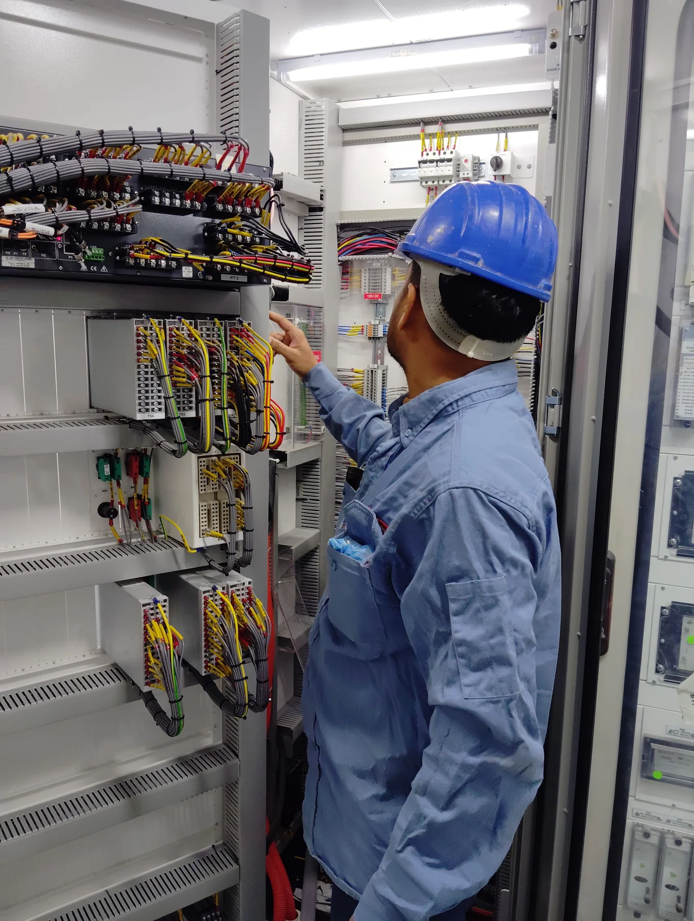
Measure the proposed footprint and the path from delivery access to the final location, then compare those conditions with equipment drawings and project requirements. Account for working clearances, doors, structural supports, overhead obstructions, cable entry and bending space, conduit locations, ventilation needs, and room for installation and future maintenance. A section that fits the lineup width may still conflict with a wall, existing cable, or building feature. Confirm floor loading and anchoring requirements with the appropriate project professionals, and determine whether site access or sequencing affects the design. These checks are especially important when extending equipment in a crowded electrical room or coordinating construction around operating facilities. Site dimensions and installation plans should be verified by the project team. Switchgear Builder Virginia can consider documented constraints when developing a custom new-equipment proposal; schedule and configuration remain subject to quote and verification.
Define Scope and Submittals
A useful request for proposal states the lineup identification, proposed location, load and system requirements, known bus information, available fault-study data, room dimensions, cable-entry preferences, and expected project interfaces. Include drawings and photographs where authorized, clearly labeled with their source and date; images alone do not establish internal construction or ratings. Ask the manufacturer to identify assumptions, required confirmations, proposed transition details, included devices, and exclusions in the submittal package. Clarify who will coordinate protection, field dimensions, installation, and any required inspections or approvals. New equipment can be custom built, and short lead times may be available, but timing depends on the verified scope and quoted schedule. For applicable low-voltage switchboard assemblies, UL 891 may apply; confirm the required construction and documentation for the specific project. Do not extend that standard to medium- or high-voltage equipment.