
SERVICES / MANUFACTURER DIRECT
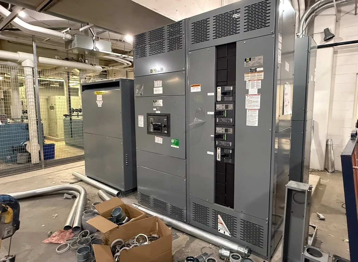
Control panel integration connects specified control devices and wiring with power equipment through clearly defined interfaces. For Switchgear Builder Virginia projects, the scope can identify which signals enter or leave the equipment, where terminals are provided, and which party supplies each component and connection. The right arrangement depends on the approved drawings, operating sequence, equipment configuration, and project responsibilities. Buyers should resolve these details before fabrication so the control interface fits the intended system without assuming unverified devices, ratings, approvals, or field work are included.
Define the interface
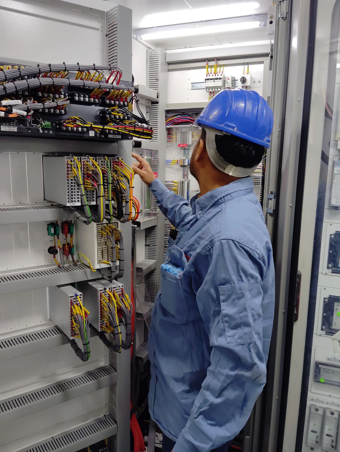
Start with a signal list that identifies each control point, its purpose, source, destination, and expected behavior. Depending on the design, interfaces may include status contacts, trip or close commands, alarms, metering signals, or communications connections. These are possible functions, not features to assume are included. Specify the signal type and electrical characteristics where known, along with normal state, fail state, and any required isolation. Also identify whether control power comes from the power equipment, an external source, or a separately specified supply. A terminal schedule can then show point names, terminal numbers, wire references, and destinations. This makes it easier for the engineer, equipment manufacturer, controls contractor, and installer to identify mismatches before construction. Confirm every interface against the project requirements and approved drawings; an ambiguous point name alone does not establish its function or compatibility.
Coordinate schematics
Schematics should explain how the specified devices relate to the equipment, not merely show a collection of symbols. Review the control narrative alongside elementary diagrams, connection diagrams, terminal plans, and device schedules as applicable to the project. Check that each command and indication has a defined source, destination, and reference, and that wire and terminal identifiers agree across documents. Device tags should match the equipment schedule and the project’s naming convention. If interlocks or permissives are required, the responsible design authority should define the intended sequence and approve its representation. Do not infer an operating sequence from a generic diagram or device label. During review, record unresolved points as questions rather than silently selecting a control method. Final drawing formats, revision responsibilities, and the drawings included with the equipment should be settled in the quote and submittal process.
Set scope boundaries
Integration scope works best when it states who furnishes, mounts, wires, and verifies each item. The equipment scope may include only the control devices and internal wiring specifically identified in the accepted documents. External sensors, PLCs, networks, field cables, conduits, programming, and connections to other packages may belong to other parties unless expressly included. Identify the physical boundary at the equipment terminals and name the party responsible for conductors beyond that point. Clarify whether terminal blocks, spare points, labels, and wiring diagrams are required, and define any quantity or arrangement in project documents. Distinguish factory-installed wiring from field termination and commissioning tasks. These boundaries help prevent assumptions about labor, software, coordination, and compatibility. Have the project team confirm the division of responsibility before release; a general phrase such as “controls included” may not define what is actually supplied.
Plan coordination
Control interfaces often depend on information from several packages, so establish a review sequence before drawings are finalized. Identify who will provide the control narrative, device data, point list, equipment drawings, and external connection details, and when each input is needed. Compare the specified devices with available enclosure space, terminal capacity, wiring routes, environmental requirements, and the equipment configuration under consideration. Any required separation of control and power wiring, shielding, grounding, or routing should be defined by the project design and verified for the selected arrangement. Avoid assuming that a particular communications protocol, enclosure feature, or device is standard. If information changes after drawing approval, document the revision and review effects on interfaces, materials, and schedule. Custom builds and short lead times may be available, but configuration, schedule, and ratings remain subject to quote and verification.
Verify before release
Before fabrication, review the interface list, schematics, terminal schedule, device data, and responsibility matrix as one coordinated package. Confirm that signal names and terminal references agree, required devices are identified, and open design questions have an assigned owner. Ask which inspection or factory checks are included in the quoted scope; do not assume a particular test, approval, listing, or field service unless it is documented. Where checks are specified, agree on their method, records, and acceptance criteria before work begins. Verify that the intended operating sequence and external connections are represented in the approved documents, while leaving system-level commissioning responsibilities clearly assigned. Switchgear Builder Virginia can review specified integration requirements for a custom build, with component selection, schedule, ratings, and scope confirmed through quotation and project documentation. Nationwide shipping is available; shipping does not establish installation or commissioning scope.