
SERVICES / MANUFACTURER DIRECT
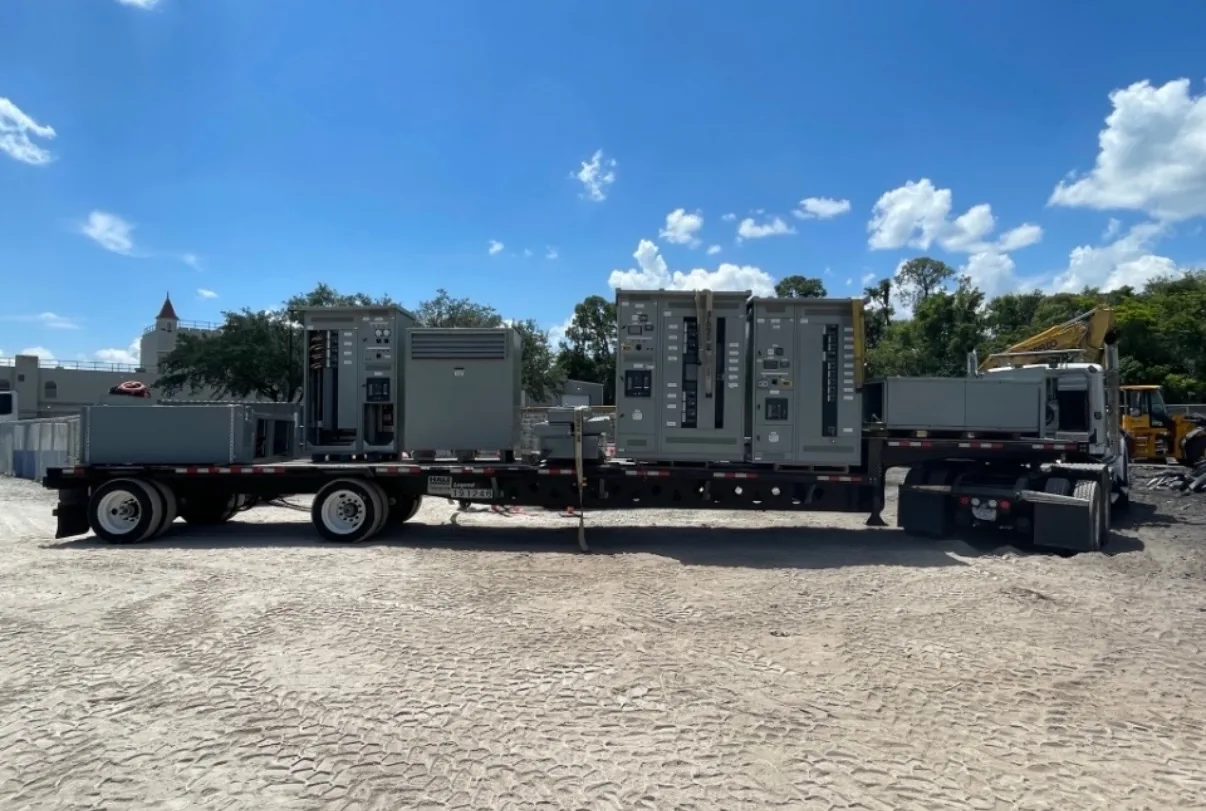
Custom switchgear starts with the project documents, not a standard lineup assumption. A one-line diagram and load schedule help define the electrical arrangement, connected loads, and likely equipment boundaries; they do not, by themselves, settle every rating or physical detail. Reviewing those inputs alongside site constraints lets buyers identify open decisions before fabrication, including protective-device selections, access needs, and approval responsibilities. Switchgear Builder Virginia manufactures custom equipment in the United States using all-American components, with short lead times subject to project scope and quote. Nationwide shipping is available. The following checkpoints can help organize a useful design review; final ratings, configuration, schedule, and applicable requirements must be verified for each project.
Start with the documents
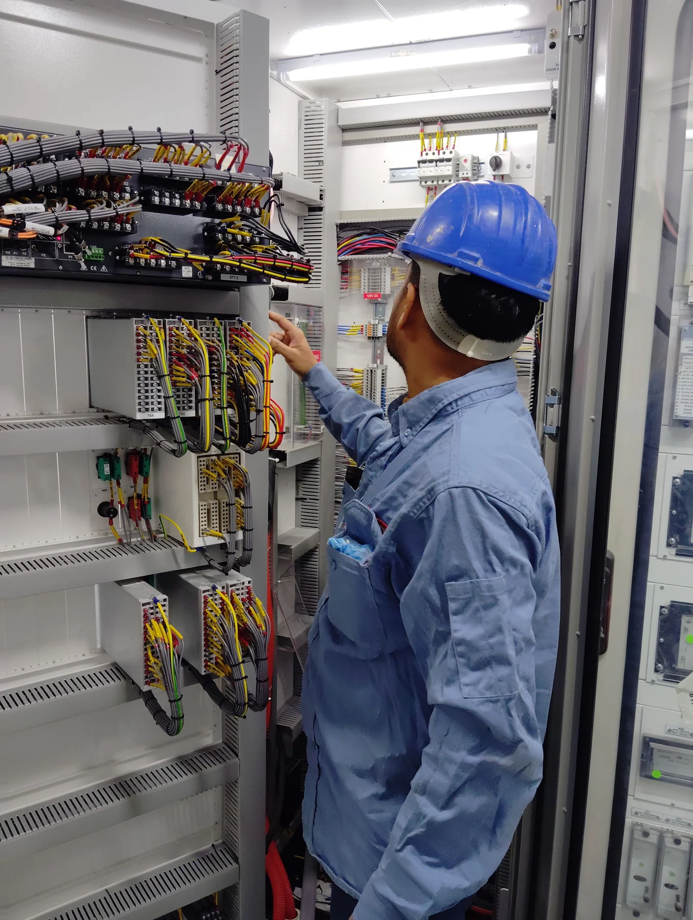
Use the latest one-line diagram as the map of sources, buses, tie points, and outgoing circuits. Pair it with a load schedule that identifies each load, expected demand, and any known starting or operating conditions. Then flag information that is missing, inconsistent, or still subject to change. For example, a feeder shown on the one-line but absent from the schedule needs clarification before its device and section can be finalized. Identify the serving system, available fault-current information, and project responsibility for confirming it; do not infer these values from a typical installation. Mark required future provisions separately from circuits needed at initial energization. This distinction can affect space planning and device coordination. A manufacturer can translate defined inputs into a proposed custom lineup, but unresolved engineering assumptions should be documented for review rather than silently treated as requirements.
Verify electrical ratings
Buyers should distinguish the ratings that describe the incoming supply from those that apply to each bus, feeder, and device. Confirm system voltage and phase, continuous current needs, and the available fault-current basis with the responsible project engineer or utility information. Interrupting ratings and assembly withstand capability are related but are not interchangeable; the required values depend on the system and proposed configuration. Where the design includes a main-tie-main arrangement or multiple sources, clarify normal operating positions and the conditions under which ties may close. Those details affect the design review and may affect protection. Do not assume that a rating shown on an older drawing remains suitable after a service change. Proposed ratings and device selections are subject to quote and verification against project documents, applicable equipment standards, and the final design.
Fit the lineup to the site
A workable lineup must fit the electrical room and support installation, operation, and maintenance. Provide available wall lengths, ceiling height, door and hallway clearances, floor conditions, and the intended cable or busway entry direction. Note whether conductors approach from above or below, and identify any structural or routing constraints that need coordination. Front-only or rear access, section arrangement, and the location of large cable compartments can change the practical footprint; verify these choices against the room plan and operating needs. Also distinguish the equipment outline from working space required around it, which must be resolved by the project team under applicable requirements. If the room layout is preliminary, identify it as such and ask which dimensions remain flexible. Custom construction can address project-specific arrangements, but a fit should not be represented as confirmed until dimensions and interfaces are reviewed.
Choose protection deliberately
The load schedule helps frame feeder-device needs, but it is not a substitute for protection coordination or a complete device specification. For each circuit, identify the served load, expected operating current, and any project-specified trip or fuse requirements. Confirm device type, frame or fuse size, trip functions, accessories, and control power only after the responsible engineer reviews the application. Selectivity, arc-energy reduction features, ground-fault functions, metering, and communications may be relevant options, but their availability and suitability must be verified for the proposed assembly. If controls or interlocks are required, provide a sequence of operation that states permitted source and tie states, alarms, and intended operator actions. Avoid relying on informal labels such as “standard protection.” A clear device schedule and control narrative reduce interpretation gaps and give reviewers a concrete basis for checking the proposed lineup before fabrication.
Close approvals before fabrication
Before release, reconcile the one-line, load schedule, equipment schedule, room plan, and device schedule so they describe the same configuration. Assign responsibility for confirming system data, protection settings, utility interfaces, control sequences, and any required project approvals. Ask which submittal drawings, review cycles, inspection steps, and test records apply; these depend on project scope and should not be assumed in advance. For applicable low-voltage switchboard assemblies, UL 891 may be relevant, subject to verification for the proposed equipment. It does not apply as a blanket statement to medium- or high-voltage switchgear. Switchgear Builder Virginia builds custom equipment in the United States with all-American components and ships nationwide. Lead times are short, but timing depends on the quoted scope and must be confirmed for the order. Ratings, approvals, tests, and schedule remain subject to project review and verification.