
TECHNICAL GUIDES / MANUFACTURER DIRECT
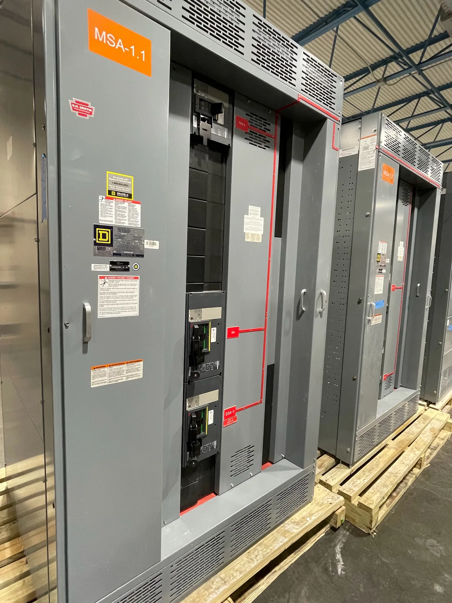
A service entrance design review checks how incoming power, service disconnects, metering, grounding and downstream distribution fit together before equipment is specified. Switchgear Builder Virginia manufactures new custom switchgear and switchboards in the USA using all-American components, with nationwide shipping and short lead times subject to project scope and quote. The review helps buyers identify decisions and open questions; the responsible design professionals and utility determine final code compliance, interface requirements and approvals.
Define the Service Boundary
Start by documenting where the utility’s responsibility ends and the customer’s electrical system begins. That boundary affects equipment ownership, metering arrangements, available fault-current information and who must review the proposed interface. Gather the utility’s service requirements, project one-line diagram, load information and any available service data before selecting an assembly. Confirm whether the service is overhead or underground, the number and configuration of incoming sources, and whether the project anticipates a future source or capacity change. These are design inputs, not assumed equipment features. A buyer should ask the engineer to identify the service point, service conductors and disconnecting means on the drawings, then compare that arrangement with the utility’s documented requirements. If the interface is not settled, record it as an open item rather than relying on a standard configuration or assuming the utility will accept a particular layout.
Coordinate Disconnects
Review the service disconnect arrangement against the one-line diagram and the project’s operating needs. Confirm the number of service disconnects, their intended grouping and identification, the equipment they supply, and whether any additional source or alternate-feed arrangement affects the layout. The design team should verify applicable disconnecting and overcurrent requirements for the project; the equipment manufacturer should receive the resulting ratings, configuration and connection details for quotation. Space, access, cable entry, bus arrangement and planned maintenance can influence the enclosure and section layout, but they do not establish an approved design by themselves. Ask whether the specified assembly is a low-voltage switchboard and whether UL 891 construction is applicable to the requested equipment. UL 891 is relevant only to applicable low-voltage switchboards, not medium- or high-voltage switchgear. Confirm requested listings and documentation for the exact quoted configuration rather than assuming every option carries the same status.
Resolve Grounding Details
Grounding and bonding should be reviewed as a coordinated system, not treated as a generic accessory selection. The engineer should define the service grounding arrangement, bonding points, grounding-electrode connections and any downstream separation requirements applicable to the project. Provide those requirements in the equipment documents so the proposed assembly can be checked against the design. Source configuration, transfer equipment and separate supplies may affect the grounding approach, so unresolved operating modes should be identified before quotation. Do not infer conductor sizes, bonding methods or code compliance from a product description; those determinations belong to the responsible electrical design professional and authority having jurisdiction. In the review, mark where grounding connections enter or leave the assembly, who supplies associated conductors, and what details still require coordination with the field installation. This makes scope gaps visible early and reduces the risk of drawings, purchased equipment and site work being based on different assumptions.
Set Metering and Utility Interface
Metering requirements can shape the service section, enclosure space, conductor routing and access provisions. Confirm whether the utility requires a particular metering method, compartment arrangement, instrument-transformer provisions, sealing access or documented clearances. These details vary by utility and project, so obtain the applicable requirements directly from the utility rather than treating a prior design as a standard. Clarify who furnishes metering components, who installs them, and which party reviews drawings before fabrication. Likewise, identify the incoming conductor details, termination provisions and utility connection sequence that the project team expects. If those inputs are pending, make them explicit quote assumptions and confirm how a later change could affect design, cost or schedule. Switchgear Builder Virginia can quote custom new equipment from defined project requirements; equipment configuration, ratings and schedule remain subject to review and verification. Shipping is nationwide, but it does not replace utility coordination or approval.
Assign Reviews and Close Gaps
Use a responsibility list to close the review: the electrical engineer establishes the design basis and code decisions; the utility confirms its service-interface and metering requirements; the equipment supplier reviews the requested construction and available product details; and the authority having jurisdiction handles approvals assigned to it. The project should identify who coordinates shop drawings, who resolves comments, and which documents must be accepted before release for fabrication. Compare the final one-line diagram, equipment schedule, service requirements and quoted configuration for consistent voltage, current, fault-duty and connection information, with each value verified for the specific project. Record deviations and unresolved items in writing instead of assuming they are covered by a general specification. When a low-voltage switchboard falls within UL 891’s scope, identify that requirement in the specification and verify the quoted assembly’s applicable status. This review organizes decisions; it does not substitute for engineering, inspection or utility approval.