
RATINGS / MANUFACTURER DIRECT
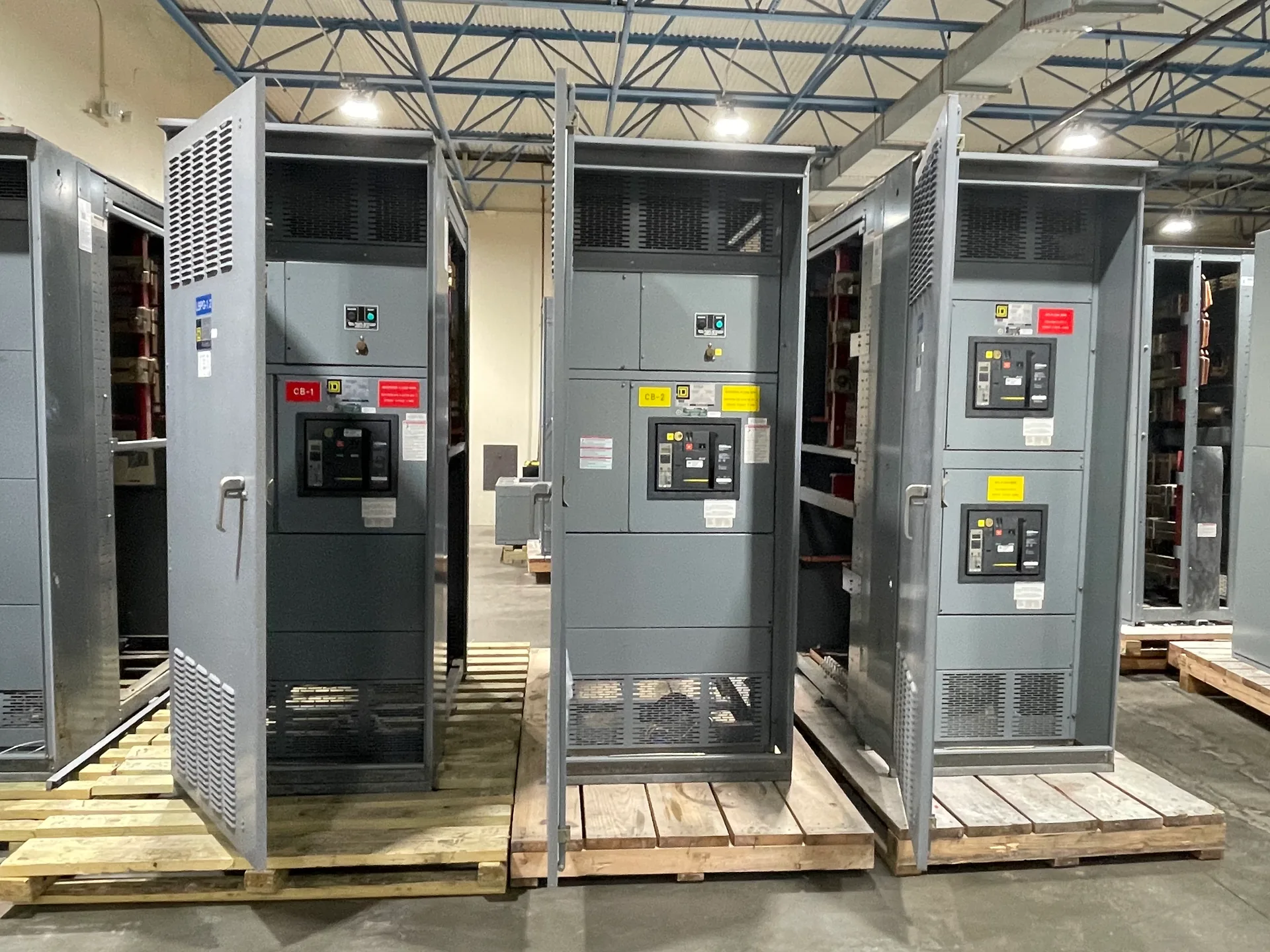
A 120/208 V three-phase system can serve both line-to-line equipment and 120 V phase-to-neutral loads, but the voltage label alone does not define a suitable assembly. Switchgear Builder Virginia develops custom new equipment around the project’s documented service, load mix, fault conditions, and distribution plan. Early decisions about neutral capacity, feeder allocation, and protective-device ratings help buyers compare configurations on a consistent basis. Applicable low-voltage switchboard assemblies may be specified to UL 891; applicability and project requirements must be confirmed. Ratings, schedules, and configuration are subject to quote and verification.
Confirm the service
Start with the actual source and service arrangement, not just “120/208 V” on a preliminary schedule. A common configuration is a grounded-wye, three-phase, four-wire service, with 208 V between phases and 120 V from each phase to neutral. Confirm the available conductors, grounding and bonding approach, service point, and whether the equipment is service entrance or downstream distribution. Those details affect the one-line diagram, incoming termination provisions, metering, and protective-device selection. A different source arrangement or site-specific requirement can change the design, even when the nominal voltage appears identical. Provide current drawings and utility or facility information for review; do not assume an existing panel nameplate proves the available fault current or exact system configuration. Switchgear Builder Virginia can develop a custom new assembly from verified project inputs, with ratings and construction confirmed during quotation.
Map the load mix
List loads by voltage and connection before settling feeder quantities or breaker frames. Single-phase 120 V loads use a phase and neutral; many three-phase loads use all three phases and no neutral, while some 208 V single-phase loads connect between two phases. Motors, receptacles, lighting, controls, and electronic equipment can therefore place different demands on the same distribution section. Record each load’s connection, nameplate information, expected operating pattern, and any required dedicated feeder. Distinguish continuous duty and planned growth using the project engineer’s criteria rather than applying an arbitrary spare-capacity percentage. A clear load schedule helps reveal whether proposed feeder spaces, conductor terminations, and device ratings fit the actual application. It also gives buyers a practical basis for comparing layouts and identifying missing information before the assembly configuration is finalized.
Size the neutral deliberately
Neutral capacity should follow the connected load and its characteristics, not a blanket assumption that every 120/208 V board needs either a reduced or oversized neutral. Phase-to-neutral loads return current on the neutral, and groups of nonlinear electronic loads may add harmonic current that matters to neutral evaluation. Ask the electrical designer to document the expected load profile, applicable design criteria, and any specified neutral rating. Confirm whether the neutral is required through the main device and feeder arrangement, and how it will be terminated and bonded for the equipment’s location in the system. Do not infer neutral ampacity from the voltage designation or from a neighboring installation. A stated neutral option is not a verified rating until it is included in the approved configuration and equipment documentation. This review helps align the proposed assembly with the intended loads without unsupported assumptions.
Balance phase-to-neutral feeders
Distribute 120 V circuits across phases with the expected demand in mind, rather than balancing only by circuit count. A branch-circuit schedule can show materially different loading when one phase serves more lighting, receptacle, or electronic loads than another. Consider operating patterns and likely simultaneous use, then review the projected phase currents and neutral current against the designer’s criteria. Feeder arrangement and spare positions can influence how easily loads are assigned or moved later, so buyers should identify foreseeable additions before the layout is settled. Balancing is an engineering and commissioning consideration, not a substitute for correctly sized conductors or protective devices. Provide the latest panel schedules and load calculations where available, and resolve discrepancies between drawings and field information before release. The goal is a documented distribution plan that supports the actual mix of 120 V and 208 V loads.
Verify protection and scope
Protective-device ratings must be selected for the documented system and application. Confirm voltage rating, continuous current, interrupting rating, available fault current, coordination objectives, and any required ground-fault functions with the responsible engineer. These values are related but not interchangeable: a suitable ampere rating alone does not establish that a device can interrupt the available fault current. Verify the main and feeder device types, trip settings or trip units, accessories, and coordination study assumptions as applicable to the project. Define metering, enclosure, cable access, termination space, and any specified control features in the equipment scope. Switchgear Builder Virginia manufactures new custom equipment in the USA with all-American components and offers nationwide shipping; schedules and ratings remain subject to quote and verification. Applicable low-voltage switchboard assemblies may be specified to UL 891 when the project and assembly warrant it.